3D Printed Normally Closed CNC Tool Height Setter
By Daniel Foote on
Recently, a business that we worked with purchased a brand new 1325 CNC router - that is a CNC router with a 1300mm x 2500mm working area, fitted with an automatic tool changer. While a fantastic machine, there were a few things missing from the machine.
One of those things was a mobile tool height setter. The Auto Tool Changer (ATC) had a special tool height sensor mounted at the back of the machine, which it used to check the tool heights. However, there was no sensor that could be used before starting a job, as many of the jobs were programmed with the Z=0 at the top of the workpiece for convenience. The machine was intended for use in a cabinet shop, where all the jobs would be programmed with Z=0 at the machine bed, but instead it was being used for a range of beautiful wood toys and furniture.
The machine used a Weihong NK105 G3 control system. It's a solid control system, but naturally has it's own quirks!
Normally Closed switch
In addition to this, after some investigation on the machine, the tool height setter was actually a normally closed switch. Other CNC machines I had worked with previously were normally open, and closed a circuit through a probe. So this meant that the approach used in the past wouldn't work on this machine! We'd actually need a switch of some kind to be able to automate this part.
Altering the wiring
Some reading of the NK105 G3 manual shows that it only has a single input pin for tool setting. So that means that the mobile tool setter needs to be inline with the existing tool setter. Such that when either of the normally closed switches are opened, it signals the controller that the tool has activated. A diagram is shown below.
Version 1 - just the micro switch
For a test, I grabbed a spare micro switch that I had on hand, and soldered on some wires. We then ran some extra wiring through the drag chains of the machine, right down to the spindle head. Then, I added the switch inline with the existing tool setter.
I then mounted the switch in between two pieces of acrylic to give it a stable platform. For our testing, we then used the tool set command on the controller (Shift + 9) and then tool started probing downwards toward the switch. The first issue that we had is that you had to have the tiny little micro switch in exactly the right position to contact the tool. Some tools might not engage the switch correctly depending on how they were rotated! The top of the micro switch was also rounded, meaning it didn't always touch the same spot each time, meaning that it wasn't that accurate.
It proved the concept though - that the switch would work and act as a mobile tool setter. So now it was a matter of coming up with something more accurate and easier to use.
Why not buy one?
Most of the cheap commercially available tool setters are the normally open type; that is just a block of metal that conducts when the tool touches it. The other easily available type are the fixed ones that sit at the back of the machine, and they tend to be quite tall.
In this instance, we decided to make one instead, to meet our design goals as shown below.
Design goals
There were two primary design goals for the tool setter:
- Be accurate down to around 0.1mm. This fits into the specifications for the jobs that are run on this machine.
- Be as thin as possible, so as not to use up any more of the Z clearance than needed. The fixed tool setters we looked at online were quite tall (100mm) which would use up most of the official 100mm clearance that the CNC router had. Sometimes, work pieces that were up to 80mm thick would be placed into the machine, and we wanted to be able to use the tool setter on these.
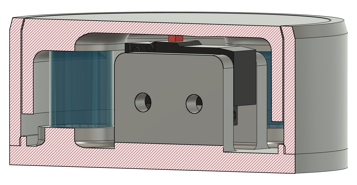
The design
So this was the design that we came up with. It just uses an ordinary sub miniature micro switch which is very common. It's designed with two 3D printed sleeves, basically, that allow the inner sleeve to move against the outer sleeve. It's designed such that they contact quite well, to prevent the platform from twisting where possible, to ensure that it consistently activates the switch at the same vertical location each time.
Internally, three springs keep the inner sleeve up against the top, and provides force for the tool to push against. The switch mounts internally with two screws to keep it securely in place and allow for a repeatable measurement.
The design ended up being three parts - the outer sleeve, the inner sleeve, and the base. The outer sleeve holds everything together and is slightly tapered at the top to keep the inner sleeve in. The inner sleeve has channels for the springs to keep them in place. The base has channels for the springs too, and for the switch to mount to.
The maximum designed travel for the sensor was 3mm, but it never actually intends to use that much - the micro switch was mounted just under the surface and should activate within 1mm of travel.
The base has a lip that's slightly bigger than the outer - it's intended to friction fit together, as I was struggling to find a good spot to add screws.
You can also view and download the design as well - it was made in Fusion 360. If you don't have Fusion 360, I've also saved the STL files here:
Printing and assembly
3D printing was straightforward, and done in PETG with standard settings. The production model didn't have a larger lip on the base, and it did friction fit - kinda! In the end we glued this one together, but I've adjusted the design since then and would make a new one differently.
I wasn't sure just how close I could make the inner sleeve to the outer sleeve; I wanted it as close as possible, but it still has to move. The first print had this gap at just 0.05mm - which was too close, unfortunately - the inner sleeve got stuck on the outer sleeve. For the second run, I increased this to 0.2mm, and this provided a really nice fit.
However, the inner sleeve still grated slightly against the outer sleeve, as the lines in the 3D print made the two contact surfaces slightly rough. This was actually an easy fix - a few moments with some sandpaper (240 grit) around the outside of the inner shell, and on the inside of the outer shell, and then they fit together and slid over each other very smoothly. To further improve this, we also added some medium thickness grease over the surfaces. Once we did this, they smoothly slid over each other without catching - just perfect for accurate measurements on the CNC.
Setup on the CNC
Although it was carefully designed, we didn't know exactly at what height the tool would engage the micro switch. This would have to be done by testing.
The CNC controller has a setting for how tall the mobile tool setter device is, in millimeters. To start with, I set this to zero, and then set up the mobile tool setter on the bed of the CNC, with a tool in place, and then ran the tool setter function. The CNC slowly moved the tool down onto the sensor until the switch triggered, and then repeated this a few times slowing down the speed each time, to get an accurate result.
Once it completed this tool setting, I then manually moved the tool down slowly until it just touched the bed, using the old "paper" trick - getting it close to the bed such that it just grabs a sheet of plain paper underneath. I know this isn't super accurate, but it's more than accurate enough for our use. Then, I took this offset and updated the CNC controller with this number.
I then repeated the automatic tool setting with the offset set. Then I moved the tool down manually again until the CNC read Z=0. I found it was off the bed by approximately 0.1mm - that is 0.1mm too far away. I added this to the existing offset in the controller, and ran the test again. This time, it was spot on the bed.
I repeated this several times, getting the same result each time. At this stage, we were ready to go!
I estimate the accuracy of this tool setter to be 0.07mm. This is well and truly appropriate for the woodworking that the machine spends most of it's life doing, so we left it as is! For other applications, you would need a higher accuracy but there are appropriate tools for those applications.
And normally open too?
There is no reason this couldn't be done with a normally open switch as well! The standard micro switches have NO and NC terminals, so it's just a matter of choosing the terminals that match your requirements. In the future, I plan to add one of these to our other CNC machines too, which have a normally open setup.
Future improvements
I stopped development at this stage as we met the goals, and I had other projects to work on! But there are a few things I would improve for a future version:
- Some kind of cable management inside the device. At the moment, the wires are hanging on by their soldering; ideally there would be some catch inside to stop the wires being stressed on their solder joints.
- Some other way to assemble the base than the friction fit. I was struggling to work in some screw positions in the base with the size I had; however, if we adjust the inside component we could free up some space for screws.