https://freefoote.net Daniel Foote 2024-03-24T05:17:24.953Z squido The personal website of Daniel Foote. Posts on random projects over the years, and an online resume of sorts. https://freefoote.net/favicon.png <![CDATA[Washing Machine Completion Monitor]]> https://freefoote.net/washing-machine-completion-monitor/ 2022-10-16T14:17:27.301Z Like many homes, we have a washing machine and dryer. But ours are a few generations back, and don't have any of the more modern Wifi features that are becoming common.

In addition, they're on the other side of the house, and we often don't hear when they finish. The net result of this is that sometimes we have wet washing left in the machine, and if left for a few days, it needs to be washed again!

So to prevent this, I added a sensor to the washing machine to send us notifications when it's completed, to allow us to empty it promptly to prevent double-washing.

This isn't at all a new or unique idea. A bit of research on the internet led me to Andrew Dupont's writeup. This used an accelerometer to tell when the machine stopped moving, and send a notification when it had determined it was finished.

Theory of operation

Like Andrew's design, I also opted to go with an accelerometer based approach, to save me having to modify the washing machine itself.

In our case, we have the dryer stacked on top of the washer, so the same sensor works for both appliances - we're not fussed which one has finished, but we want to know when both machines are idle. (So we can load the washing into the dryer, but we can't do that until the dryer is also idle, so this works!)

In a nutshell, we keep an eye on the raw accelerometer values, and distill them into a single movement figure. When this figure is above a threshold for long enough, we consider the machine running. Then, when it drops below this threshold for a period of time, it's considered idle again. The timeouts are to allow for short term quiet periods; for example the washing machine will often come to a complete halt for 20-30 seconds during it's cycle to allow the water to settle and then it will start up again; we need to consider this as a continuous operation.

Once the algorithm determines that it's running or idle, it can then send the relevant notifications; in our case via the Pushover service.

As far as the communication goes - I kept the code on the device very simple; just doing basic calculations and reporting data every 10 seconds. The data was then sent via MQTT to a Node-Red server, which then determined from that data if the machine was running or not. The Node-Red server then sent the Pushover notifications as needed.

Hardware

It turns out I had a M5Stack M5StickC-Plus on the shelf; I'd purchased it for another project, but no longer needed it. This contains everything we need for the project; a built in accelerometer, a display, Wifi, and a suitably powerful processor.

It also came with an extra bonus - internally it contains a magnet which means I can just magnet it to the washing machines - no other mounting hardware was required. This was an unexpected bonus!

The device also comes with a Micropython firmware (well, a M5Stack variant of it) which made for quick coding on the device. The code is fairly lightweight and thus didn't need the complexity of coding in C.

Phase 1

Firstly, I had to collect some raw data to work out what readings meant "working" and what readings meant "idle". I felt that the best way to do this was simply to code a very simple program on the device that reported raw accelerometer values via MQTT every second. On my server, I then subscribed to that topic and piped it all to a file for later processing.

On the M5StickC, this is the program that reported the values:

# boot.py
print("Boot setup; Wifi!")

import wifiCfg
wifiCfg.autoConnect(lcdShow=True)

# main.py
from m5stack import *
from m5ui import *
from uiflow import *
import json
from m5mqtt import M5mqtt
import imu

print("Main program startup...")

setScreenColor(0x111111)

# MQTT setup.
m5mqtt = M5mqtt(
    'washing',
    server='xxxx',
    port=1883,
    user='xxxx',
    password='xxxx',
    keepalive=60,
    ssl=False,
    ssl_params=None
)

# Start connection
print("MQTT connection.")
m5mqtt.start()

# IMU init.
print("IMU Init")
imu0 = imu.IMU()

# UI setup.
XL = M5TextBox(50, 5, "0", lcd.FONT_DejaVu40, 0xFFFFFF, rotate=90)
YL = M5TextBox(85, 80, "0", lcd.FONT_DejaVu40, 0xFFFFFF, rotate=90)
ZL = M5TextBox(50, 150, "0", lcd.FONT_DejaVu40, 0xFFFFFF, rotate=90)

def update_data():
    acc = imu0.acceleration
    XL.setText("%.2f" % acc[0])
    YL.setText("%.2f" % acc[1])
    ZL.setText("%.2f" % acc[2])

    m5mqtt.publish('washingmachine/raw', json.dumps(acc))
    print(json.dumps(acc))

while True:
    update_data()
    wait_ms(1000)

And then on my server, I just dumped the values to a file:

# mosquitto_sub -v -h localhost -p 1883 -t 'washingmachine/raw' -u xxxx -P xxxx >> wmr.txt

After a few days, and a few runs of the washing machine, I had some data:

# tail wmr.txt
washingmachine/raw [0.0, -0.181, 1.042]
washingmachine/raw [-0.003, -0.18, 1.052]
washingmachine/raw [0.005, -0.185, 1.036]
washingmachine/raw [0.006, -0.181, 1.033]
washingmachine/raw [0.006, -0.178, 1.039]
washingmachine/raw [0.009, -0.181, 1.031]
washingmachine/raw [0.012, -0.18, 1.043]
washingmachine/raw [0.009, -0.175, 1.031]
washingmachine/raw [0.012, -0.167, 1.037]
washingmachine/raw [0.01, -0.189, 1.042]

Now it's time to come up with the algorithm to work out when the machine is running or not! I happened to have PHP handy for this one on the server in question, so the prototype script was written in PHP. No reason it couldn't have been any other language; this just happened to work for me!

I wasn't as fancy as Andrew with his system and state machine. I just had a basic algorithm. In short, it just worked out the combined threshold figure, and then averaged this over 10 seconds, and I called every 10 seconds a bucket. Then, there was a simple threshold - if it was above the threshold for a few buckets, it was considered "busy", and then when it dropped below the threshold for a few buckets, it then became idle. I made them constants at the top of the script, and reran the script a few times adjusting it until the output looked like I expected it to look.

Here is the script:

<?php

// Raw input line looks like this:
// washingmachine/raw [-0.033, 1.019, 0.083]

// Slurp them into memory. We've got heaps, right?
$lines = file('wmr.txt');

$readings = array();
foreach ($lines as $line) {
	$bits = explode("washingmachine/raw", $line);
	$raw = json_decode($bits[1]);
	$readings[] = $raw;
}

// Now the constants used in the algorithm later on.
const BUCKET_LENGTH = 10;
const MOVEMENT_AVERAGE = 0.12;
const ON_TIME_THRESHOLD = 6; // in bucket lengths
const OFF_TIME_THRESHOLD = -6; // in bucket lengths

// Ignore the first 3600 readings (1 hour) - I was moving
// the sensor into place and got some random readings.
$readings = array_slice($readings, 3600);

// Split the 1 second reading into bucket sizes.
$buckets = array_chunk($readings, BUCKET_LENGTH);

// A function called for each bucket to summarize it.
function processBucket($bucket) {
	$last = null;

	$minL = 10;
	$maxL = -1;
	$sumL = 0.0;
	$countL = 0;

	foreach ($bucket as $reading) {
		if (!is_null($last)) {
			$deltaX = abs($reading[0] - $last[0]);
			$deltaY = abs($reading[1] - $last[1]);
			$deltaZ = abs($reading[2] - $last[2]);

			$force = $deltaX + $deltaY + $deltaZ;

			$minL = min($minL, $force);
			$maxL = max($maxL, $force);
			$sumL += $force;
			$countL += 1;
		}

		$last = $reading;
	}

	// I've used bcmul() to round off the digits,
	// but it is slower than using floating points.
	return array(
		'min' => bcmul($minL, '1.00', 2),
		'max' => bcmul($maxL, '1.00', 2),
		'avg' => bcmul($sumL / $countL, '1.00', 2)
	);
}

// Our kinda-state machine state.
$state = 0;
$stateCounter = 0;
$stateChangeTime = 0;

// Index loosely equals seconds, as the data points are one per second.
$index = 0;

foreach ($buckets as $bucket) {
	$result = processBucket($bucket);

	if ($result['avg'] > MOVEMENT_AVERAGE && $state == 0) {
		// Currently "off", and we're above the movement threshold, increase the counter.
		$stateCounter += 1;
	} else if ($result['avg'] < MOVEMENT_AVERAGE && $state == 1) {
		// Currently "on", and we're below the movement threshold, decrease the counter.
		$stateCounter -= 1;
	}

	if ($state == 0) {
		// Is currently off - should transition to on?
		if ($stateCounter >= ON_TIME_THRESHOLD) {
			$state = 1;
			$stateCounter = 0;

			echo "OFF FOR: ", ($index - $stateChangeTime) * BUCKET_LENGTH, " seconds\n";
			echo "State change -> ON\n";

			$stateChangeTime = $index;
		}
	} else if ($state == 1) {
		// Is currently on - should transition to off?
		if ($stateCounter <= OFF_TIME_THRESHOLD) {
			$state = 0;
			$stateCounter = 0;

			echo "ON FOR: ", ($index - $stateChangeTime) * BUCKET_LENGTH, " seconds\n";
			echo "State change -> OFF\n";

			$stateChangeTime = $index;
		}
	}

	$index += 1;
}

And with my test data, it gave me this result, which matched what I had in my mind. There are still some false positives, but this bucket size gave me reasonable results.

I'm happy with a few false positives as we'll know when we've had it on or off.

# php wmr.php
OFF FOR: 166080 seconds
State change -> ON
ON FOR: 80 seconds
State change -> OFF
OFF FOR: 60 seconds
State change -> ON
ON FOR: 110 seconds
State change -> OFF
OFF FOR: 33370 seconds
State change -> ON
ON FOR: 4070 seconds
State change -> OFF
OFF FOR: 100 seconds
State change -> ON
ON FOR: 1450 seconds
State change -> OFF
OFF FOR: 81730 seconds
State change -> ON
ON FOR: 2900 seconds
State change -> OFF
OFF FOR: 222980 seconds
State change -> ON
ON FOR: 2800 seconds
State change -> OFF
OFF FOR: 8620 seconds
State change -> ON
ON FOR: 310 seconds
State change -> OFF
OFF FOR: 90000 seconds
State change -> ON
ON FOR: 1290 seconds
State change -> OFF
OFF FOR: 2840 seconds
State change -> ON
ON FOR: 4510 seconds
State change -> OFF
OFF FOR: 8450 seconds
State change -> ON
ON FOR: 1470 seconds
State change -> OFF

Phase 2

With an algorithm that I'm happy with, it's time to make something for production use! To save having to fetch and reprogram the sensor all the time, I decided to make the sensor just collate the readings into 10 second buckets and report that value via MQTT.

So on the sensor, the code was changed to:

from m5stack import *
from m5ui import *
from uiflow import *
import json
from machine import Pin, I2C
from m5mqtt import M5mqtt
import imu

print("Main program startup...")

setScreenColor(0x111111)

# MQTT setup.
m5mqtt = M5mqtt(
    'washing',
    server='xxxx',
    port=1883,
    user='xxxx',
    password='xxxx',
    keepalive=60,
    ssl=False,
    ssl_params=None
)

# Start connection
print("MQTT connection.")
m5mqtt.start()

# IMU init.
print("IMU Init")
imu0 = imu.IMU()

# UI setup.
XL = M5TextBox(50, 5, "0", lcd.FONT_DejaVu40, 0xFFFFFF, rotate=90)
YL = M5TextBox(85, 80, "0", lcd.FONT_DejaVu40, 0xFFFFFF, rotate=90)
ZL = M5TextBox(50, 150, "0", lcd.FONT_DejaVu40, 0xFFFFFF, rotate=90)

last = None
bucket = []

def update_data():
    global last
    global bucket

    acc = imu0.acceleration
    XL.setText("%.2f" % acc[0])
    YL.setText("%.2f" % acc[1])
    ZL.setText("%.2f" % acc[2])

    if last is not None:
        deltaX = abs(acc[0] - last[0])
        deltaY = abs(acc[1] - last[1])
        deltaZ = abs(acc[2] - last[2])

        force = deltaX + deltaY + deltaZ

        bucket.append(force)

    if len(bucket) == 10:
        avg = sum(bucket) / len(bucket)
        bucket = []

        print("10s average", avg)
        m5mqtt.publish('washingmachine/10s', "%0.4f" % avg)

    last = acc

    print(json.dumps(acc))

while True:
    update_data()
    wait_ms(1000)

Then, in my node-red instance I set up the following nodes:

The Node-red nodes

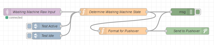
The meat of this is in the decision function node. It re-implements what we had in the PHP script, but with a few minor differences. It uses the context available to the function, but that applies only to this function. In my Node-red instance, I've configured a persistent save location for this data which was needed for other things that my Node-red instance does. If you don't have this configured, it'll be lost each time you restart Node-red.

But the code mostly speaks for itself below!

// Parse the value into a float.
var avg = parseFloat(msg.payload);

// Our hard-coded threshold and settings.
var MOVEMENT_AVERAGE = 0.12;
var ON_TIME_THRESHOLD = 6; // in bucket lengths
var OFF_TIME_THRESHOLD = -6; // in bucket lengths

// Reload our context.
var state = context.get('state') || 0;
var stateCounter = context.get('stateCounter') || 0;
var stateChangeTime = context.get('stateChangeTime') || Date.now();

// Determine where we're at.
if (avg > MOVEMENT_AVERAGE && state == 0) {
    stateCounter += 1;
} else if (avg < MOVEMENT_AVERAGE && state == 1) {
    stateCounter -= 1;
}

var newMessage = null;
var now = Date.now();

// node.warn("Now is " + now);

if (state == 0) {
    // Is off - should transition to on?
    if (stateCounter >= ON_TIME_THRESHOLD) {
        state = 1;
        stateCounter = 0;

        var offFor = now - stateChangeTime;
        newMessage = {}
        newMessage.payload = true;
        newMessage.duration = offFor;

        stateChangeTime = now;
    }
} else if (state == 1) {
    // Is on - should transition to off?
    if (stateCounter <= OFF_TIME_THRESHOLD) {
        state = 0;
        stateCounter = 0;

        var onFor = now - stateChangeTime;
        newMessage = {}
        newMessage.payload = false;
        newMessage.duration = onFor;

        stateChangeTime = now;
    }
}

// node.warn("State " + state + " state counter " + stateCounter + " stt " + stateChangeTime);

// Save our context.
context.set('state', state);
context.set('stateCounter', stateCounter);
context.set('stateChangeTime', stateChangeTime);

// Return the new message. If there is no change,
// this will be null causing it not to emit the message.
return newMessage;

And then the tiny node to format this for Pushover. Basically, we ignore if it turns on; we're only interested when it turns off.

var newMessage = null;

if (msg.payload) {
    // Ignore... we won't notify when it starts.
} else {
    var timeLength = Math.floor(msg.duration / 1000);
    newMessage = {};
    newMessage.topic = "Washing machine or Dryer finished after " + timeLength + " seconds";
    newMessage.payload = "Time to empty!";
}

return newMessage;

It then gets routed into a pushover node, using the standard Node-red pushover node. I created an application for Home automation messages, and then added our device keys to the node. (They don't appear in the export below for security reasons!)

For completeness, here is the JSON export from Node-red:

[
    {
        "id": "04569ce94308cf33",
        "type": "tab",
        "label": "Flow 2",
        "disabled": false,
        "info": "",
        "env": []
    },
    {
        "id": "7dc3c88ef8ad68a6",
        "type": "mqtt in",
        "z": "04569ce94308cf33",
        "name": "Washing Machine Raw Input",
        "topic": "washingmachine/10s",
        "qos": "2",
        "datatype": "utf8",
        "broker": "b093c481fe186acb",
        "nl": false,
        "rap": true,
        "rh": 0,
        "inputs": 0,
        "x": 160,
        "y": 60,
        "wires": [
            [
                "00d5be41e5bdc801"
            ]
        ]
    },
    {
        "id": "00d5be41e5bdc801",
        "type": "function",
        "z": "04569ce94308cf33",
        "name": "Determine Washing Machine State",
        "func": "// Parse the value into a float.\nvar avg = parseFloat(msg.payload);\n\n// Our hard-coded threshold and settings.\nvar MOVEMENT_AVERAGE = 0.12;\nvar ON_TIME_THRESHOLD = 6; // in bucket lengths\nvar OFF_TIME_THRESHOLD = -6; // in bucket lengths\n\n// Reload our context.\nvar state = context.get('state') || 0;\nvar stateCounter = context.get('stateCounter') || 0;\nvar stateChangeTime = context.get('stateChangeTime') || Date.now();\n\n// Determine where we're at.\nif (avg > MOVEMENT_AVERAGE && state == 0) {\n    stateCounter += 1;\n} else if (avg < MOVEMENT_AVERAGE && state == 1) {\n    stateCounter -= 1;\n}\n\nvar newMessage = null;\nvar now = Date.now();\n\n// node.warn(\"Now is \" + now);\n\nif (state == 0) {\n    // Is off - should transition to on?\n    if (stateCounter >= ON_TIME_THRESHOLD) {\n        state = 1;\n        stateCounter = 0;\n        \n        var offFor = now - stateChangeTime;\n        newMessage = {}\n        newMessage.payload = true;\n        newMessage.duration = offFor;\n        \n        stateChangeTime = now;\n    }\n} else if (state == 1) {\n    // Is on - should transition to off?\n    if (stateCounter <= OFF_TIME_THRESHOLD) {\n        state = 0;\n        stateCounter = 0;\n        \n        var onFor = now - stateChangeTime;\n        newMessage = {}\n        newMessage.payload = false;\n        newMessage.duration = onFor;\n        \n        stateChangeTime = now;\n    }\n}\n\n// node.warn(\"State \" + state + \" state counter \" + stateCounter + \" stt \" + stateChangeTime);\n\n// Save our context.\ncontext.set('state', state);\ncontext.set('stateCounter', stateCounter);\ncontext.set('stateChangeTime', stateChangeTime);\n\n// Return the new message. If there is no change,\n// this will be null causing it not to emit the message.\nreturn newMessage;",
        "outputs": 1,
        "noerr": 0,
        "initialize": "",
        "finalize": "",
        "libs": [],
        "x": 500,
        "y": 60,
        "wires": [
            [
                "56764b0aabc085ab",
                "7ae019ac7f3d83e2"
            ]
        ]
    },
    {
        "id": "56764b0aabc085ab",
        "type": "debug",
        "z": "04569ce94308cf33",
        "name": "",
        "active": true,
        "tosidebar": true,
        "console": false,
        "tostatus": false,
        "complete": "true",
        "targetType": "full",
        "statusVal": "",
        "statusType": "auto",
        "x": 790,
        "y": 60,
        "wires": []
    },
    {
        "id": "2f51cc59ab47e1a5",
        "type": "inject",
        "z": "04569ce94308cf33",
        "name": "Test Active",
        "props": [
            {
                "p": "payload"
            },
            {
                "p": "topic",
                "vt": "str"
            }
        ],
        "repeat": "",
        "crontab": "",
        "once": false,
        "onceDelay": 0.1,
        "topic": "washingmachine/10s",
        "payload": "0.35",
        "payloadType": "str",
        "x": 220,
        "y": 120,
        "wires": [
            [
                "00d5be41e5bdc801"
            ]
        ]
    },
    {
        "id": "623e6c7622f31eb5",
        "type": "inject",
        "z": "04569ce94308cf33",
        "name": "Test Idle",
        "props": [
            {
                "p": "payload"
            },
            {
                "p": "topic",
                "vt": "str"
            }
        ],
        "repeat": "",
        "crontab": "",
        "once": false,
        "onceDelay": 0.1,
        "topic": "washingmachine/10s",
        "payload": "0.05",
        "payloadType": "str",
        "x": 220,
        "y": 160,
        "wires": [
            [
                "00d5be41e5bdc801"
            ]
        ]
    },
    {
        "id": "7ae019ac7f3d83e2",
        "type": "function",
        "z": "04569ce94308cf33",
        "name": "Format for Pushover",
        "func": "var newMessage = null;\n\nif (msg.payload) {\n    // Ignore... we won't notify when it starts.\n} else {\n    var timeLength = Math.floor(msg.duration / 1000);\n    newMessage = {};\n    newMessage.topic = \"Washing machine or Dryer finished after \" + timeLength + \" seconds\";\n    newMessage.payload = \"Time to empty!\";\n}\n\nreturn newMessage;",
        "outputs": 1,
        "noerr": 0,
        "initialize": "",
        "finalize": "",
        "libs": [],
        "x": 540,
        "y": 140,
        "wires": [
            [
                "56764b0aabc085ab",
                "dca8df092dea0d17"
            ]
        ]
    },
    {
        "id": "dca8df092dea0d17",
        "type": "pushover",
        "z": "04569ce94308cf33",
        "name": "Send to Pushover",
        "device": "",
        "title": "",
        "priority": 0,
        "sound": "",
        "url": "",
        "url_title": "",
        "html": false,
        "x": 810,
        "y": 140,
        "wires": []
    },
    {
        "id": "b093c481fe186acb",
        "type": "mqtt-broker",
        "name": "FAFF MQTT",
        "broker": "xxxx",
        "port": "1883",
        "clientid": "",
        "autoConnect": true,
        "usetls": false,
        "protocolVersion": "4",
        "keepalive": "60",
        "cleansession": true,
        "birthTopic": "",
        "birthQos": "0",
        "birthPayload": "",
        "birthMsg": {},
        "closeTopic": "",
        "closeQos": "0",
        "closePayload": "",
        "closeMsg": {},
        "willTopic": "",
        "willQos": "0",
        "willPayload": "",
        "willMsg": {},
        "sessionExpiry": ""
    }
]

Results

It works! Now it's just up to the human factor of paying attention to the notifications unloading the machine once it finishes. We'll just have to see how that goes...!

Future improvements

While it works, there is still a bit of a grey area in determining if the machine is working or not. For more accuracy, we'd need to modify the washing machine's wiring, or use something pointed at the control panel to tell if it's done.

But for now, it works!

]]>
<![CDATA[Virtual USB flash drive for a non-networked CNC router]]> https://freefoote.net/virtual-usb-flash-drive-for-a-non-networked-cnc-router/ 2022-07-09T11:13:27.301Z Recently, a business that we worked with purchased a brand new 1325 CNC router - that is a CNC router with a 1300mm x 2500mm working area, fitted with an automatic tool changer. While a fantastic machine, there were a few things missing from the machine.

The machine uses a Weihong NK105 G3 control system. It's a solid control system, but naturally has it's own quirks! One of the main issues we had with the machine is that the only way to get jobs onto the machine is via a USB drive. It has no networking options at all. This was known before the machine was purchased; to save costs, this controller was selected rather than an upgraded one that had networking functionality.

This CNC router is working on a wide variety of different jobs each day, which can involve several dozen plug-unplug cycles on both the CNC router and the computer used to generate the gcode for the machine. This adds wear and tear to all the components involved, not to mention the reaching up and down to where the drive is located on the machine.

But that doesn't mean we can't network it...

A quick bit of internet research shows that a Raspberry Pi Zero's USB ports have a gadget mode - such that you can actually use it to create a virtual USB drive. So while we can't fully network the device, we can at least stop the constant tumble of unplugging and re plugging in a USB drive all the time.

The goal of this project was simple - just set up a Raspberry Pi Zero to act as a USB flash drive, and allow it to accept file updates from a remote computer over the network.

Once the files are available to the CNC, jobs were started from the control handle on the CNC. Once the job is loaded into memory on the CNC controller, you can actually disconnect the USB flash drive, which means that we can reload new files while the current job is in progress.

Overview

In this specific case, the user of the CNC machine works on a Mac laptop, and they use Fusion 360 to generate toolpaths. This allowed me to take a few shortcuts with the development of this project!

Fusion 360 typically post processes files into a single folder; and it's often easier just to use a single folder for this. This gives us a single source of files to send to the CNC.

Then, as it was a Mac laptop, it already comes with rsync, which is a battle hardened way to transfer files via a network reliably, so why not make use of it, rather than reinventing the wheel in a less perfect way?

The user in question is tech savvy; we created a shortcut for them to be able to quickly sync the Fusion 360 folder over to the virtual drive.

For other users, I would deploy this a bit differently - I was originally going to find a simple web-based file manager that allowed uploading of files, and set that up on the Raspberry Pi, and modifying it a touch to allow you to manually mount or unmount the virtual drive. However, time is money, and this solution robustly met the requirements with minimal time, although it's not the most user friendly solution.

Hardware

The core hardware required is:

  • A Raspberry Pi Zero. I used a W model with built in 2.4GHz wireless. However, through other technical limitations in the destination workshop, we only had 5GHz wireless available, meaning we needed to Ethernet connect the Raspberry Pi Zero to another 5GHz wireless router to get everything to work.
  • A micro SD card for the Raspberry Pi. It'll need to be big enough for the OS and also extra space for the virtual flash drive. I used a 16GB one, with a 2GB virtual drive, which is more than adequate for our use. The largest gcode files we work with are only around 5MB, but they average much smaller.
  • Either: ** A USB A-to-A cable, and then a USB micro to female A cable, joined together; ** or a USB male A to Micro USB male cable.
  • A power supply for the Raspberry Pi (powering it from the CNC controller is possible, kinda, but when you virtually disconnected the flash drive, the CNC controller dropped power temporarily on the USB port causing the Raspberry Pi to reboot. So external power is necessary).

And optional hardware, which was needed due to our specific setup:

  • An external Ethernet board. We used an ENC28J60 based adapter which communicates via SPI with the Raspberry Pi. There are other boards available for the Raspberry Pi Zero that offer extra USB ports and an Ethernet port via a RealTek chip, however, these boards take over the USB port and add a USB hub, and prevents the gadget mode from working correctly. The ENC28J60 board uses SPI and thus doesn't take over the USB port. ENC28J60 modules are commonly available very cheaply in a variety of forms.
  • An external WiFi router in client mode if needed, to connect via Ethernet. In our case, we used a TP-LINK WA1201 AC1200, as it was readily available and was one of the cheapest that properly supported client mode.

Setup of the Raspberry Pi Zero

We flashed Raspbian Lite using the official imaging tool on a Windows machine. At time of writing this was 2022-04-04, and the 32bit version.

When using the imaging tool, we used the advanced configuration to set:

  • WiFi credentials (for setup and testing purposes, as everything was configured and tested in a different workshop from where it was ultimately installed)
  • Password for the "pi" user
  • Hostname (I used "cncdrive" making the hostname "cncdrive.local", but adjust for your setup)
  • Timezone
  • Enable SSH

After it was flashed, the card was inserted and the Pi was booted. I connected to it via SSH, and checked that it expanded the filesystem correctly to the full drive. You can also take this time to apply other standard setup steps for your environment, like installing monitoring tools and so forth.

Set up the gadget mode overlay

We need to enable the gadget overlay, and get it to insert the module at boot.

# sudo nano /boot/config.txt
... at end add:
dtoverlay=dwc2

# sudo nano /etc/modules
... at end add:
dwc2

Now reboot the Pi, and we'll create the filesystem.

Creating the filesystem

Firstly we create the file that will be the virtual block device:

# sudo dd bs=1M if=/dev/zero of=/drive.bin count=2048

I then connected it to a Windows 10 machine and got it to partition the block device and format it. Yes, technically I could have done this all with Linux, but I was aiming for compatibility with the CNC router, which worked more reliably with drives formatted by a Windows machine.

To get it to expose the file as a block device over USB ("plugging in" the USB drive):

# sudo modprobe g_mass_storage file=/piusb.bin stall=0

Then using a Windows machine, partition the drive and format it - we used FAT32 to get the compatibility we needed. When you're done, you can release the block device as follows ("unplugging" the USB drive):

# sudo modprobe -r g_mass_storage

Now we'll set up the mount point on the Pi.

# sudo mkdir /mnt/drive

Then comes the interesting part. Basically, we're using rsync as a destination, without a password or encryption. (Yes, this is insecure, but it's on a private network and we're aiming for simplicty in this instance). Before the transfer starts, rsync runs an "early exec" script, which unmounts the virtual drive from the CNC, and then remounts the filesystem locally, allowing the file transfer to take place. After the sync, it runs a "post-xfer exec" script, which umounts the drive from Linux and re-exports it to the CNC. As mentioned before, this was the quickest and most robust solution to meet this specific users requirements, although it's not super user friendly.

So let's set up Rsync. Turns out that systemd has solid additional default settings used to harden rsync installations. These settings are ideal for almost all installations of rsync - except for ours! So we had to relax the systemd rules slightly to allow our very unusual disc usage pattern.

Let's loosen the systemd rules for rsync slightly, to allow the exec scripts to be able to mount filesytems and run modprobes. Without this change, the scripts will fail to run. I did spend a good 30 minutes working this one out:

# sudo vim /lib/systemd/system/rsync.service
... modify:
PrivateDevices=off

# sudo systemctl daemon-reload

Now let's configure the rsync daemon:

# sudo vim /etc/rsyncd.conf

... the entire contents of this file should be:

uid = root
gid = root
max connections = 10
socket options = SO_KEEPALIVE

[cnc]
path = /mnt/drive
comment = CNC Drive
read only = false
early exec = /home/pi/pre-copy.sh
post-xfer exec = /home/pi/post-copy.sh

Set up the early exec script. Note this can't be a "pre-xfer exec" as it's not early enough in the transfer; rsync already has aquired file handles for the folder, and doesn't see the mount point made inside the script. Yes, this took a few goes to work out...!

# sudo vim /home/pi/pre-copy.sh
#!/bin/bash -x

set -e

echo "Removing from CNC..."
sudo modprobe -r g_mass_storage

sleep 1

echo "Mounting drive locally..."
sudo mount -o loop,offset=65536,sizelimit=2144337920 /drive.bin /mnt/drive

sleep 1

echo "Ready to receive files."

Wait a sec! What's happening here? For simplicity, I'm not setting up a loopback mount device for the file which would allow us to address the partions separately, as this was extra configuration and more complexity. Instead, I worked out the offset and partition size from the file image, and put them into the mount command, bypassing the need to set up a loopback device. The numbers below will be different for your device, but it gives you an idea. (Snippet originally from StackExchange) Note that the numbers are in sectors, so multiply them by 512 (in this case) to get the actual physical numbers for the mount command.

# sudo fdisk -lu sda.img
...
Units = sectors of 1 * 512 = 512 bytes
Sector size (logical/physical): 512 bytes / 512 bytes
...
  Device Boot      Start         End      Blocks   Id  System
sda.img1   *          56     6400000     3199972+   c  W95 FAT32 (LBA)

And the post copy script, to unmount the drive and expose it to the CNC again. Note that it uses the "ro=1" flag for g_mass_storage, meaning that the CNC has a read only view of the virtual drive. There isn't a specific need for this, but there also isn't a reason for the CNC controller to manage files on the drive.

# sudo vim /home/pi/post-copy.sh
#!/bin/bash -x

set -e

echo "Unmounting drive..."
umount /mnt/drive

echo "Re-exporting mass storage..."
modprobe g_mass_storage file=/drive.bin stall=0 ro=1

echo "Completed."

And finally, a script to execute on boot, which exposes the drive to the CNC on boot.

# sudo vim /home/pi/on-reboot.sh
#!/bin/bash -x

set -e

echo "Exporting mass storage..."
/usr/sbin/modprobe g_mass_storage file=/drive.bin stall=0 ro=1

echo "Completed."

Make all these scripts executable:

# sudo chmod a+x /home/pi/*.sh

And start rsync:

# sudo systemctl restart rsync

And we're going to use crontab to run the on-boot script to expose the drive. There are other ways to accomplish this, but this is the way I chose to do it:

# sudo crontab -e
...
@reboot /home/pi/on-reboot.sh

And we're ready to test! At this stage, if you reboot the Pi and connect to it via USB, you should get a virtual flash drive. Now, if you're ready to send files to it, you can simply use this rsync command. This will work from a Linux or Mac host directly without any additional software to install in most cases. You'll see the drive vanish from your computer when you start the transfer, and then re-appear shortly afterwards:

# rsync --progress --recursive --verbose --delete source/* rsync://cncdrive.local/cnc

It should give you progress as it transfers the files, and will delete on remote so that the remote folder looks exactly like your local source folder.

Adding Ethernet

As mentioned before, in our specific installation, we didn't have 2.4GHz wireless available at the installation location, but only 5GHz wireless. So we had to add an external ethernet device to the setup.

This was based on the Raspberry Pi Spy's instructions although our module was different to the one pictured, and had different markings on the pins. Also, the documentation for our module had some inconsistencies too which led to some confusion. But here is the lowdown:

  • The documentation for the module we had said it was to be powered by 5V, but the IO level was 3.3V (compatible with the Pi Zero), but this was in fact a lie, and we had to power the module from 3.3V to get it to work.
  • I originally had the MISO & MOSI pins swapped causing it not to work. On our module, the pins as labelled SI and SO, and they're opposite on the Pi - that is, connect Pi->MISO to Module->SI and Pi->MOSI to Module->SO. Read it as "serial in" and "serial out" and it starts to make sense!
  • Our module had a MAC address already assigned to it, and didn't need us to choose a MAC address or set this at boot.

Once wired up, setting up the Pi was very simple:

# sudo nano /boot/config.txt

... add or alter:
dtparam=spi=on
dtoverlay=enc28j60

# sudo reboot

On reboot, the ethernet port will appear as eth0, and automatically aqcuire an address via DHCP if it can. It's actually that simple...! I was surprised actually by just how easy the ethernet setup was.

Installation

For installation, I made a small panel out of acrylic that the Raspberry Pi Zero and the ENC28J60 modules were screwed to, to keep them together. Then we made a larger box to house the wireless router, USB power supply for the Pi, and a powerboard. This kept all the components safe and shielded them from the very dusty woodworking shop that they were installed into. This box was mounted on a wall near the CNC router, and the USB A-to-A cable was used to connect to the CNC. The A-to-A cable was 3 meters long allowing us to route the USB cable out of the way, and it just plugged into the front panel of the CNC router.

Should the Raspberry Pi Zero fail, we can easily unplug it from the CNC router and resume using the USB thumb drive as we used to do, allowing us to keep working even if it fails.

Results

A week after the installation, the user of the machine was very happy with this addition to their CNC router. It's saved them a lot of time swapping USB drives and has made for a much easier workflow for them, as they're often tweaking or adjusting gcodes for various jobs, so as to get the perfect results. Even though it's not that user friendly, everything is handed by a single click on the Mac, so it's more than easy enough to use for this application.

Future improvements

With more time, we'd make a few improvements to the system:

  • Use a password and/or encryption when talking to rsync. In our installation, this was basically the only device on this segment of the network, so we can work around not having additional security.
  • Add a web-based file manager with some extras onto the device. This would then allow use from a Windows computer via a web browser instead. A quick search shows a couple of simple open source projects which would be a good starting point for a basic web file manager, allowing uploads and deletes. We'd have to expand it slightly to allow manually "unplugging" the USB drive and "plugging" it back in, but this should be straight forward to add to an existing system.
]]>
<![CDATA[3D Printed Normally Closed CNC Tool Height Setter]]> https://freefoote.net/3d-printed-normally-closed-cnc-tool-height-setter/ 2022-06-26T11:13:27.301Z Recently, a business that we worked with purchased a brand new 1325 CNC router - that is a CNC router with a 1300mm x 2500mm working area, fitted with an automatic tool changer. While a fantastic machine, there were a few things missing from the machine.

One of those things was a mobile tool height setter. The Auto Tool Changer (ATC) had a special tool height sensor mounted at the back of the machine, which it used to check the tool heights. However, there was no sensor that could be used before starting a job, as many of the jobs were programmed with the Z=0 at the top of the workpiece for convenience. The machine was intended for use in a cabinet shop, where all the jobs would be programmed with Z=0 at the machine bed, but instead it was being used for a range of beautiful wood toys and furniture.

The machine used a Weihong NK105 G3 control system. It's a solid control system, but naturally has it's own quirks!

Normally Closed switch

In addition to this, after some investigation on the machine, the tool height setter was actually a normally closed switch. Other CNC machines I had worked with previously were normally open, and closed a circuit through a probe. So this meant that the approach used in the past wouldn't work on this machine! We'd actually need a switch of some kind to be able to automate this part.

Altering the wiring

Some reading of the NK105 G3 manual shows that it only has a single input pin for tool setting. So that means that the mobile tool setter needs to be inline with the existing tool setter. Such that when either of the normally closed switches are opened, it signals the controller that the tool has activated. A diagram is shown below.

Version 1 - just the micro switch

For a test, I grabbed a spare micro switch that I had on hand, and soldered on some wires. We then ran some extra wiring through the drag chains of the machine, right down to the spindle head. Then, I added the switch inline with the existing tool setter.

I then mounted the switch in between two pieces of acrylic to give it a stable platform. For our testing, we then used the tool set command on the controller (Shift + 9) and then tool started probing downwards toward the switch. The first issue that we had is that you had to have the tiny little micro switch in exactly the right position to contact the tool. Some tools might not engage the switch correctly depending on how they were rotated! The top of the micro switch was also rounded, meaning it didn't always touch the same spot each time, meaning that it wasn't that accurate.

It proved the concept though - that the switch would work and act as a mobile tool setter. So now it was a matter of coming up with something more accurate and easier to use.

Why not buy one?

Most of the cheap commercially available tool setters are the normally open type; that is just a block of metal that conducts when the tool touches it. The other easily available type are the fixed ones that sit at the back of the machine, and they tend to be quite tall.

In this instance, we decided to make one instead, to meet our design goals as shown below.

Design goals

There were two primary design goals for the tool setter:

  1. Be accurate down to around 0.1mm. This fits into the specifications for the jobs that are run on this machine.
  2. Be as thin as possible, so as not to use up any more of the Z clearance than needed. The fixed tool setters we looked at online were quite tall (100mm) which would use up most of the official 100mm clearance that the CNC router had. Sometimes, work pieces that were up to 80mm thick would be placed into the machine, and we wanted to be able to use the tool setter on these.

The design

So this was the design that we came up with. It just uses an ordinary sub miniature micro switch which is very common. It's designed with two 3D printed sleeves, basically, that allow the inner sleeve to move against the outer sleeve. It's designed such that they contact quite well, to prevent the platform from twisting where possible, to ensure that it consistently activates the switch at the same vertical location each time.

Internally, three springs keep the inner sleeve up against the top, and provides force for the tool to push against. The switch mounts internally with two screws to keep it securely in place and allow for a repeatable measurement.

The design ended up being three parts - the outer sleeve, the inner sleeve, and the base. The outer sleeve holds everything together and is slightly tapered at the top to keep the inner sleeve in. The inner sleeve has channels for the springs to keep them in place. The base has channels for the springs too, and for the switch to mount to.

The maximum designed travel for the sensor was 3mm, but it never actually intends to use that much - the micro switch was mounted just under the surface and should activate within 1mm of travel.

Cutaway view of the CNC height sensor.

The base has a lip that's slightly bigger than the outer - it's intended to friction fit together, as I was struggling to find a good spot to add screws.

You can also view and download the design as well - it was made in Fusion 360. If you don't have Fusion 360, I've also saved the STL files here:

Printing and assembly

3D printing was straightforward, and done in PETG with standard settings. The production model didn't have a larger lip on the base, and it did friction fit - kinda! In the end we glued this one together, but I've adjusted the design since then and would make a new one differently.

I wasn't sure just how close I could make the inner sleeve to the outer sleeve; I wanted it as close as possible, but it still has to move. The first print had this gap at just 0.05mm - which was too close, unfortunately - the inner sleeve got stuck on the outer sleeve. For the second run, I increased this to 0.2mm, and this provided a really nice fit.

However, the inner sleeve still grated slightly against the outer sleeve, as the lines in the 3D print made the two contact surfaces slightly rough. This was actually an easy fix - a few moments with some sandpaper (240 grit) around the outside of the inner shell, and on the inside of the outer shell, and then they fit together and slid over each other very smoothly. To further improve this, we also added some medium thickness grease over the surfaces. Once we did this, they smoothly slid over each other without catching - just perfect for accurate measurements on the CNC.

Setup on the CNC

Although it was carefully designed, we didn't know exactly at what height the tool would engage the micro switch. This would have to be done by testing.

The CNC controller has a setting for how tall the mobile tool setter device is, in millimeters. To start with, I set this to zero, and then set up the mobile tool setter on the bed of the CNC, with a tool in place, and then ran the tool setter function. The CNC slowly moved the tool down onto the sensor until the switch triggered, and then repeated this a few times slowing down the speed each time, to get an accurate result.

Once it completed this tool setting, I then manually moved the tool down slowly until it just touched the bed, using the old "paper" trick - getting it close to the bed such that it just grabs a sheet of plain paper underneath. I know this isn't super accurate, but it's more than accurate enough for our use. Then, I took this offset and updated the CNC controller with this number.

I then repeated the automatic tool setting with the offset set. Then I moved the tool down manually again until the CNC read Z=0. I found it was off the bed by approximately 0.1mm - that is 0.1mm too far away. I added this to the existing offset in the controller, and ran the test again. This time, it was spot on the bed.

I repeated this several times, getting the same result each time. At this stage, we were ready to go!

I estimate the accuracy of this tool setter to be 0.07mm. This is well and truly appropriate for the woodworking that the machine spends most of it's life doing, so we left it as is! For other applications, you would need a higher accuracy but there are appropriate tools for those applications.

And normally open too?

There is no reason this couldn't be done with a normally open switch as well! The standard micro switches have NO and NC terminals, so it's just a matter of choosing the terminals that match your requirements. In the future, I plan to add one of these to our other CNC machines too, which have a normally open setup.

Future improvements

I stopped development at this stage as we met the goals, and I had other projects to work on! But there are a few things I would improve for a future version:

  • Some kind of cable management inside the device. At the moment, the wires are hanging on by their soldering; ideally there would be some catch inside to stop the wires being stressed on their solder joints.
  • Some other way to assemble the base than the friction fit. I was struggling to work in some screw positions in the base with the size I had; however, if we adjust the inside component we could free up some space for screws.
]]>
<![CDATA[Resume]]> https://freefoote.net/resume/ 2022-06-26T00:00:00.000Z This page is a work in progress. Over time, I will update this with my resume.

Really, I promise!

In the meantime, please get in touch if you have any questions.

]]>
<![CDATA[TV Content Based Backlight]]> https://freefoote.net/tv-content-based-backlight/ 2013-08-01T11:13:27.301Z Quite a while ago someone told me about the Ambilight system that was incorporated into certain TVs. I was intrigued by the concept, and wondered if it would catch on.

Whilst it didn't seem to catch on in too many consumer TV sets, it did seem to catch on with DIYers in general. I've seen quite a few different types around the place, and most of them involve quite a bit of wiring to get enough resolution around the TV edges. The extensive wiring turned me off, as it's a lot of work to put together and maintain, let alone if you need to move the TV around.

But just a few months ago I came across the WS2812 family of RGB LEDs. These nifty little devices allow you to chain a series of them with just a single input to drive them. They also have a constant current source inside each chip, meaning that the colours and brightness are more stable across a series of these chips - anyone who's bought cheap 12V LED strips off various internet sites will know that the LEDs can vary quite a bit.

I first saw them on Adafruit's web store. They'd already written an Arduino library, and written up how to use them properly, especially with their very tight timing requirements to send data to them. I certainly applaud Adafruit for making their library public, and I feel bad that it's significantly more expensive to source parts through them or a reseller, as I live in Australia.

A few weeks after seeing them in Adafruit's store, I randomly happened to search for them to see where else I could get them from, and stumbled across an eBay listing, which offered a 5 metre strip for $60 (with 30 LEDs per metre), from a seller in Hong Kong. Having ordered items from overseas on many occasions, I was used to the 4 or so week lead time on items from Hong Kong. I ordered it just to see what would happen.

Whilst it was coming, I realised that I could use the strip to build my own version of an Ambilight, something that I'd been keen to try for some time.

A section of WS2812 LED strip.

Capturing the Screen

A problem that anyone who builds an Ambilight system runs into is how to actually figure out what colours to show for each region of the screen.

In an ideal world, you would put something inline with the HDMI input to the TV (especially if you already have a home theatre receiver doing the HDMI switching for you), and it would pick colours for you and use them. In practice, this isn't so easy. To start with, HDMI is a high bandwidth bus - you need specialised chips and probably a FPGA to process that data. And if that wasn't enough - there is HDCP, meaning that the signal is encrypted between the two.

One of the best systems that I've seen used a HDMI splitter, then an HDMI to S-Video converter, and finally a microprocessor that reads the S-Video to sample the colours for the display. This is a good approach, but it's higher cost than I would like - and if you don't get a suitable HDMI splitter, you lose HDCP, and finally, there is an analog component to the system.

I'll continue to research some simple way to read in HDMI data (and see about the DMCA issues with that too).

In the meantime, that leaves screencapture as the only other way to get the data. This also restricts input sources to be computers, unfortunately, but it's the cheapest way to get everything to work together.

Parts List

The following parts were what I ended up using for my system.

  • Arduino Uno R3
  • Wiznet based Arduino Ethernet shield
  • 5 metre long WS2812 LED strip
  • Molex connector
  • Hookup wire

Hardware - LEDS

I'm very fortunate to have a Sharp 70" TV that I acquired when I moved into my new house in February 2013. After a month or so, I wall mounted it to give me more options with the other equipment in the theatre.

Most Ambilight systems are fitted to smaller TVs. So when you actually do the measurements of the actual edge of the LCD panel, you end up with just short of 5 metres.

After measuring the LCD panel, and rounding to the nearest LED cut point on the strip, I cut the LED strip and soldered each end together. For where I have the hardware, I started at the bottom left corner, went right, then up, then left and finally down again. With 30 LEDs/metre, I ended up with 46 LEDs across, and 26 LEDs high. (Or 144 channels if you wanted to think of it that way).

The LED strip that I bought conveniently has a 3M branded peel off sticky back. So, with the assistance of a friend, we simply stuck the LED strip to the edges of the back of the TV in the order I had decided.

The only remaining connections were for 5V power, and the single data input wire for the Arduino. For power, I temporarily soldered on a molex connector and powered it from a desktop computer that I have in the theatre.

The top right corner, showing how the sections were soldered together and held down with tape.

The bottom left corner, showing the end point connection.

A front view of where the connection to the TV is placed.

Hardware - driver

To drive the system, I used an Arduino Uno R3 that I had sitting around the place. I also had an ethernet shield spare, which turned out to be an excellent addition.

The hardware side is very simple. Attach ethernet shield to Arduino, and then plug in the ground and driver pin for the LED strip. The Arduino is currently powered via USB off the desktop computer in the theatre.

The stacked Arduino and Ethernet shield, on an insulating box.

Firmware - Arduino

The Arduino sketch is pretty simple. It revolves around two different types of UDP packets sent to it via the network.

The first packet type is just 6 bytes long, and is an input select packet. It contains a magic constant to indicate what it is, and then another byte to select what input, and finally four more bytes that are the colour to set the entire strip to.

The second packet type is up to 606 bytes long in my sketch. To make it longer, you'll have to modify the sketch. This packet contains the magic byte to indicate it contains pixel data, then another byte to say what input it's for. If the input byte doesn't match the current input (set with the input packet type), the rest of it is ignored. If it does match, the next two bytes indicate how many pixels follow. After that is the pixels, 32 bits each. All of these multi byte values are assumed to be in the correct byte order for AVR microcontrollers (little endian). You'll see later the computer software changes the byte order before the packets even leave the computer, to save trying to wangle byte orders on the Arduino itself.

When the Arduino gets a pixel packet, it just writes the pixels out onto the strip directly. It doesn't do anything special for synchronisation.

The sketch I used is checked into the tv-backlight repository on Github.

Sofware - The prototype

My initial temporary target platform was Windows. I had a movie day planned a week ahead, and had chosen Windows as the playback platform for a few reasons relating to the performance of my home network. It's a long story.

Anyway, I knew I was going to have to delve into some deep graphics related code, and graphics coding is one of my weak points. So, purely to get it working, I wrote a Python script on my Linux desktop to prototype it. I ended up using GTK, thinking that it would allow me to test the prototype on Windows as well, and even OSX.

The Python script grabbed the screen, calculated the edge pixels, and sent off the UDP packet, and then repeated this forever.

To calculate the edge pixels, I cheated somewhat. After taking the screenshot (at 1920x1080), I resized it down to the number of pixels on the TV (46x26), which dropped back to some nice fast C code. The resize took less than a millisecond to complete. I used the nearest interpolation method so it would choose hard values for each pixel, rather than trying to smooth them with the adjacent pixels. After it was resized, it's a lot more feasible to scan the edges with Python.

Python also contains the super helpful struct library, which made it trivially easy to take the colours and convert them into binary data (with the appropriate byte order) for the UDP packets.

On my Linux machine, Ubuntu 12.04 with compositing turned on, the GTK screen capture took about 350ms. The rest of the processing and UDP sending accounted for another 5ms or so. So the prototype worked, and worked accurately, but it wasn't fast enough.

The scripts I used are checked into the tv-backlight repository on Github.

Software - Windows

For kicks, I decided to install Python 2.7, PyGTK, and Scipy on my Windows desktop to see how that did. Predictably, it was capturing frames in 2.7 seconds, and then completing the processing in another few milliseconds. So I asked a friend who is much more conversant in graphics programming about a better way to capture frames in Windows 7. The short answer was "this is a rabbit hole". His only suggestion was to disable Aero and see if that helped.

So disable Aero I did. Suddenly, my Python script was capturing frames at 40FPS - including a 1080p video in VLC - and passing that long to the LED strip. In realtime, the effect was quite spectacular and exactly what I had been trying to build!

With some more tweaking - specifically to average several frames together to stop instant changes in the scene causing flashing, and code to detect the black bars in theatrical style widescreen videos, the system was production ready for a Lord of the Rings marathon. 12 hours of 1080p video later, and neither the computer nor the Arduino showed any signs of stopping.

Interestingly enough, I later tried to run the Python script on my Linux laptop, which is fitted with an Intel HD3000 graphics chipset. With compositing turned on, it was capturing at upwards of 80 frames per second.

Some other testing revealed that the script isn't able to capture DirectX surfaces. Some games that I tried did work with quirks, and other games just came up black to the script. To fix this properly, I suspect something using DirectX (or even something lower level) will be required to get it to work.

Sofware - OSX

My primary media centre is a Mac Mini running Plex. So having it working great on a Windows machine wasn't that useful to me. However, the Python script didn't want to work on the Mac, and my simple attempts to install PyGTK on the Mac resulted in something weird that didn't work...

A little bit of Googling showed that OSX ships with Python Objective C bindings, which allow access to core graphics. After some copy and pasting of examples from StackOverflow, I had my script updated to capture images and process them. CoreGraphics was a lot lower level than I expected, so rather than trying to figure out how to get it to composite the average image like the PyGTK one does, I hacked together a simple numerical averaging algorithm to compare frames.

On OSX, the end result is a Python script that can capture and send frames anywhere from 40 to 70 frames per second. The net result is a very nice ambilight system for my media centre.

Switching inputs

When I built my home theatre setup in February 2013, I was pleasantly surprised that basically everything was IP controllable. The only item that wasn't IP controllable was my cheapy DealExtreme LED strip lighting, which required IR signals. I had a spare iTach IR gateway, so everything became IP controllable.

Rather than toting three remotes to control everything, I wrote a simple Python web application, affectionately called Theaterizr, which I access through my Android phone. It's also accessable via my partner's iPhone too, which was the reason for making it a web app. This web app is organised into scenes, and as you enter each scene, it sends the appropriate IP commands to the devices to configure them correctly - much easier for my partner to use than juggling three remote controls!

Because I have this web application already, I can hook it to send input switch commands to my Arduino. This means I can have the ambilight script running all the time on the Windows desktop and the Mac desktop, and the Arduino will simply ignore any packets that don't match it's input.

Quirks and limitations

The first quirk is that the WS2812 LEDs are very, very bright. In fact, they were too bright and drowned out the TV when I first set them up. To get around this, the script divides the colour values by two to half their brightness. This obviously isn't colour correct, but worked well enough for my setup.

The other quirk was the colour definition. Yellows and Reds show up fantastically and match the screen colours almost exactly. Greens are close to the screens colours, but not exact. And blue seems to be quite different from what's on the screen. I don't really know much about colour and colour systems, but I suspect the difference is for two reasons. The first being that I adjusted the TV with the help of a friend to make the colours work better on my TV set. The second reason is that the wall colour isn't white. It's a Dulux colour called "Buff It" which probably interferes with the blue mostly.

Enhancements to come

There are still a few enhancements to be made to this system. But they are relatively minor:

  • Neaten up the connection to the TV. It shouldn't be visible from the front, and I plan to affix the Arduino to the TV somehow and route the connections along with the other cabling for the TV.
  • Replace the power supply with a standalone one. Currently, the desktop computer has to be on to power the strip. I've ordered seperate 5A power supplies, and I just need to hook them up instead. The only quirk is that the 5M strip, at full white brightness, is rated for about 10A.

Building your own

If you would like to build your own system, here are a few notes about the code and system that I've published:

  • You can affix the LED strips in any order to your TV. If you use a different order to mine, you'll need to update your script to send the pixels in the correct order. You should be able to see in the code where this is, and it would just be a matter of rearranging the order of the for loops to achieve this.
  • Power supply. The 5M WS2812 strip is rated to draw about 10 amps at full brightness. Make sure you have a suitable power supply to back it up. A standalone computer power supply, regardless of it's rating, should be suitable to power the strip. If you're using a power supply that's in a computer, check to make sure you have enough margin to run the LED strip on it.
  • Network. Don't forget to update the IP addresses (and possibly MAC address) in the Arduino sketch, so it matches your network environment.
]]>
<![CDATA[Rain-testing via the internet sprinkler controller (old)]]> https://freefoote.net/rain-testing-via-the-internet-sprinkler-controller/ 2005-06-26T11:13:27.301Z The sprinkler controller described here applies to my previous house. The controller worked flawlessly for four years. The new owners of the house wanted a traditional controller, so it was uninstalled and replaced.

Wow! This is an old project. Your milage may vary with this project. You might want to look into Tasmota on an ESP32 based chip for the microcontroller aspects of this project. Or even into the OpenSprinkler project which can do most of this already and is in fact what I'm currently using at my current home.

When I bought my first house, the gardens attached to it had reticulation in them already, which was great. The lawn was not reticulated, but it turns out that an appropriate hose had been placed near the lawn, but never hooked up to sprinklers. So it wasn't too hard a job to reticulate the lawn as well.

However, the one thing about the reticulation is that there were a series of valves. You turned on the valve that you wanted, and then the tap, and then the garden got watered.

Which is all good and well. In Perth we have some serious (and much needed) water restrictions relating to the watering of gardens. You can only water your garden two days a week, on a roster based on the last digit on your house number. (My last digit is 5, which makes my watering days Sunday and Wednesday). The other restriction is that you have to water before 9AM, or after 6PM - and only in one of those two intervals for that day (ie, you can't water Sunday morning and Sunday night too).

I personally got irritated by having to manage the sprinklers. You'd have to turn them on, time them for a few minutes, and then switch to another station. Being the lazy person that I am, I figured I had to automate the whole system.

So that's what I did. The current system is probably what you would call version 2.

Some parts of the system were scavenged parts. That is why the hardware is kinda ugly... but amazingly enough, the system works, and hasn't broken down since its construction.

Features of my System

The current system has these features:

  • Controller board is an ethernet-based single board computer that serves up its own web pages. You can directly view the status of the device and manually turn on stations from a web browser.
  • Sprinklers are activated from entries in my crontab on my personal file server, which is populated from a schedule entered into Google Calendar.
  • If there has been more than a certain ammount of rain in the last few days, as seen by the nearest Weather station, the reticulation is not turned on.

Ideally it would contain a rain sensor here that it collects data from, rather than viewing the rainfall at the nearest government weather station, which is just over 6 kilometres away, but this system works well enough.

Version One

The original version of this sprinkler controller was serially controlled instead. The controller was a small PIC16F series microcontroller, with a simple program I found on the net. You passed it serial bytes which told it which outputs to turn on; and it did that. That was about as complicated as the controller got.

I actually used a PIC experimenters kit that I built quite a few years ago as the base for the project. I connected the serial output to my terminal server, so that I could ethernet-enable this sprinkler controller (I have an ancient Lantronix ETS16P terminal server - it was a cheapy on Ebay).

Other than that, version one did not differ from the current version.

Hardware

Solenoids and plumbing

At the local Bunnings I acquired four water solenoids. They are 24VAC soleniods that you just connect inline to the pipes in question. I bought ones that matched the pipes I already had, so they were pretty easy to hook up.

You can see them in the photo below.

Sprinkler Manifold with solenoids

The valves were existing, and I just cut the pipes at the appropriate spots and inserted the solenoids. Originally I just had the three solenoids - but I quickly found out that it was impossible to prevent the supply side from leaking, no matter what I did to it. So I then added the master valve, and kept whatever was on the supply side of that as tight as possible. It still leaks a little, but not much at all (much, much less than a dripping tap).

Because of the master valve, you have to open one of the other valves first (to select what to water) and then open the master valve. Turning the sprinklers off is just reversing this proceedure.

Relay board

As the solenoids were 24VAC, you can't just hook a pin from a PIC up to them and have it work (PICs are pretty good, but that's a little out of their range). So, you need relays to turn on the solenoids

And then you need a 24VAC power source. Which are, surprisingly, not that common (at least, when you're scrounging for parts). However, I have a weakness for fairy lights - and as such have quite a number of sets of fairy lights. Naturally, some of these are really cheap and nasty - and poorly made. I had one such set of lights where 60% of the lights stopped working (and yes, I did go through and replace globes to no avail)

  • so I chucked them. However, it conveniently had a 24VAC plugpack to power the lights...
  • so I appropriated it for this project.

Then comes the relay board. I had some relays sitting in my cupboard that I had pulled out of some other piece of equipment a long time ago. They had a 9VDC coil, but could switch up to 110VAC through them. Perfect!

I also needed to step down the 24VAC to 9VDC for the relays, and also for the ethernet controller board (which can take 7-35V DC, but not AC). So I put together a simple 7809-based regulator circuit to step the voltage down. (The version of the regulator circuit shown in the photos is hardware version 2 - I managed to blow up the first version, but that was me being silly and just soldering the parts together, and not to veroboard like you see in the photos.)

Below is a schematic for the power supply:

Power Supply Schematic

You still can't power a relay from a PIC pin. So I dug up a few NPN transistors, a few resistors (all spares in my cupboard), a bit of veroboard, and created the monstrosity that is my relay board.

Below is a schematic of what the relay board looks like. Only one of the four identical relay circuits is shown.

Sprinkler Relay Schematic

Below is a photo of the relay board, on both sides. As you can see, it's really, really ugly. Pretty much to the point where I'm embarassed to publish it on the internet.

Top view of relay board

Bottom view of relay board

Here is the power supply (before it got converted into the cooling stack, more details on that later):

Power supply for relays

Ethernet Controller board

The ethernet controller board is a SBC45 from Modtronix, in Queensland, Australia. It is a neat little board - comes with a PIC18F452, a 32k serial EEPROM, RTL8019 ethernet controller. It also has a chip to bring the RS232 outputs up to RS232 levels.

Below is a photo of the board itself.

SBC

Below is a photo of the soldered connections to the board.

SBC with soldered outputs

Hooking it all together

Connecting the relay board to the ethernet controller was quite simple. I chose to solder the wires between the two. Not quite sure why, but I don't expect to make too many changes.

After that the rest of the connections are fairly straightforward. Below is a photo of all the parts connected together, on the bench.

Sprinkler Controller Boards connected together

Installation into a weatherproof box

This is yet another ugly part of the project. I stuffed all the electronics into a weatherproof box, so it could be mounted outside, near the solenoids that it controls.

The boards are held down by sticky pads that you can put cable ties through. No doubt this is going to fall apart inside the box, probably during summer...

Below is a photo showing the layout of the parts inside the box.

Sprinkler Controller in weatherproof box

The Cooling Stack

Future Daniel to past Daniel: just use an off the shelf buck/boost module. So much more efficient than a linear regulator that I used at the time, and it won't get hot like mine did!

You can see in the photos up until this point that I just bolted a lump of aluminium to the 7809 regulator on the power supply in an attempt to keep it cool. However, at idle, the plate still got quite hot to the touch - hot enough that I couldn't hold it with my fingers for more than a few seconds. Not really something you want to have inside the box...

And why, you may ask, did it get hot if it isn't drawing much power? When you do the maths on it - the incoming voltage is 24VAC, which we convert to DC. Due to the poor regulation of the plugpack, it's more like 30VAC incoming. Once rectified, it's still 28VDC. The 7809 regulator then has 28VDC on one side and 9VDC on the other side. If it draws up to 1 amp of current (as it is designed to do at peak), it has to dissipate 19W of heat. (28V - 9V times 1A). At idle (say 100mA) it only dissipates 1.9W of heat - still enough to require some better heatsinking.

My final solution required another hole in the box. I got a lump of 40mm2 steel tube, and bolted that to the top of the box. The 7809 is then bolted to the inside of this tube. This does the job and dissipates all of the heat. After installation, the system survived a 44°C day, so I figure the cooling is adequate.

Below are a few construction photos of it. I chose to move the capacitors into the stack too, but the ends were covered with heatshink before they were placed into the tube, to prevent any shorts.

Sprinkler Stack, Side

Sprinkler Stack, End

Sprinkler Stack, On box

Final Installation outside

The whole setup was eventually fixed to the wall near the sprinklers. I placed it high up so it was just under the eaves, to keep it out of the sun.

In the end I decided to feed both power and ethernet via two CAT5 cables. Both cables run back to the rack in my storeroom - one was terminated at both ends with RJ45 jacks and hooked up to the ethernet switch. The other cable had a DC power connector soldered on to it at the rack end - to prevent me trying to plug it into a RJ45 socket - and then had the transformer plugged into that. This also keeps the transformer inside and away from the weather (it was an 'indoor only' transformer anyway).

Below are two photos of the setup, one before I siliconed up all the holes, and another after the job was complete.

Sprinkler Controller on Wall

Sprinkler Controller On Wall

Software

On the ethernet controller board

The ethernet controller board already comes with a built in webserver and set of pages.

You can download new web pages to it via FTP, so I just replaced the existing index.htm, and added an index.cgi. These pages are really simple - they just provide buttons to toggle each sector, and also a button to turn all outputs off.

Sprinkler Webpage screenshot

The firmware that comes with the controller board is not 100% perfect, though. I was hoping to get away without having to flash the controller, but I was unable to do so.

In the end, only two changes were required to the firmware. The first one was to initialise all the outputs to off when the system started. Before I made this change, the outputs would randomly be on or off when the power was applied to the system - obviously unacceptable, as you could easily have the sprinklers turn on, and the system wouldn't realise!

The other change I made was to the inbuilt FTP server. It didn't respond to the BIN command, which meant that UNIX ftp clients tried to upload the files in ASCII mode, which resulted in a broken web pages image. After this change, the system worked perfectly.

On the server

Cron Entries from Google Calendar

To get the cron entries from Google Calendar, I hacked together a python script to download an iCal (.ics) version of the relevant calendar, and then parse it, and create cron entries/

When I wrote it I was being quite lazy and I looked around for an iCal library. There doesn't seem to be too many good complete libraries for iCal. In the end I found one that would parse an iCal file, and then be able to answer the query, "are there any events X days from now". So I do this from tomorrow up to seven days from now, and parse those events into appropriate crontab entries - absolute entries, with the date in them. (So they are all one-shot).

A quick python module to read and write the current users crontab allowed for relatively simple modifiation of the users crontab. The entries are in their own comment-delimited section at the bottom of the users crontab, leaving other existing entries untouched.

This script is kinda wierd: in one sense, it's way underengineered; and in another sense, it is way overengineered. What happens to the calendar events is described in a ini file, which in my case looks like this: (as you can see, this is the overengineered bit)

[global]
daysahead = 7

[calendars]
watering = http://www.google.com/calendar/ical/[snip - contains private UID here]/basic.ics

[commands]
watering = sprinklers raincheck

[cmd-sprinklers]
# match contains named match groups: (?P<foo>.*)
# oncommand contains printf string for python, where %(foo)s is
#    replaced with named "foo" from match
# Special items available: (these take precendence over the ones from match)
# calendar = symbolic name of calendar (from above)
# date     = date of run (ontime) (string in YYYY-MM-DD)
# time     = time of run (ontime) (string in HH:MM:SS)
# offdate  = offdate (string in YYYY-MM-DD) (Only if offcommand is set)
# offtime  = offtime (string in HH:MM:SS)   (Only if offcommand is set)
# duration = duration (string in seconds, eg, 3600)

match = Garden Water (?P<area>\w+)
oncommand  = /home/daniel/sprinklers/sprinkler-control-wrapper %(area)s on
offcommand = /home/daniel/sprinklers/sprinkler-control-wrapper %(area)s off

[cmd-raincheck]
match = Rain Check
oncommand = cd /home/daniel/sprinklers; ./rain-last-few-days.py

This results in the following crontab for my user:

# Update the local crontab from Google Calendar. 00:10 each day.
10 0 * * * cd /home/daniel/icaltocron; ./icaltocron.py

# ICALTOCRON-START
# Automatically generated - if you edit, any changes will be removed
# next time icaltocron is run.
27 6 23 9 * /home/daniel/sprinklers/sprinkler-control-wrapper frontgarden on
37 6 23 9 * /home/daniel/sprinklers/sprinkler-control-wrapper frontgarden off
16 6 23 9 * /home/daniel/sprinklers/sprinkler-control-wrapper backgarden on
26 6 23 9 * /home/daniel/sprinklers/sprinkler-control-wrapper backgarden off
5 6 23 9 * /home/daniel/sprinklers/sprinkler-control-wrapper lawn on
15 6 23 9 * /home/daniel/sprinklers/sprinkler-control-wrapper lawn off
0 6 23 9 * cd /home/daniel/sprinklers; ./rain-last-few-days.py
27 6 26 9 * /home/daniel/sprinklers/sprinkler-control-wrapper frontgarden on
37 6 26 9 * /home/daniel/sprinklers/sprinkler-control-wrapper frontgarden off
16 6 26 9 * /home/daniel/sprinklers/sprinkler-control-wrapper backgarden on
26 6 26 9 * /home/daniel/sprinklers/sprinkler-control-wrapper backgarden off
5 6 26 9 * /home/daniel/sprinklers/sprinkler-control-wrapper lawn on
15 6 26 9 * /home/daniel/sprinklers/sprinkler-control-wrapper lawn off
0 6 26 9 * cd /home/daniel/sprinklers; ./rain-last-few-days.py
27 6 30 9 * /home/daniel/sprinklers/sprinkler-control-wrapper frontgarden on
37 6 30 9 * /home/daniel/sprinklers/sprinkler-control-wrapper frontgarden off
16 6 30 9 * /home/daniel/sprinklers/sprinkler-control-wrapper backgarden on
26 6 30 9 * /home/daniel/sprinklers/sprinkler-control-wrapper backgarden off
5 6 30 9 * /home/daniel/sprinklers/sprinkler-control-wrapper lawn on
15 6 30 9 * /home/daniel/sprinklers/sprinkler-control-wrapper lawn off
0 6 30 9 * cd /home/daniel/sprinklers; ./rain-last-few-days.py
# ICALTOCRON-END

You can download the whole icaltocron script.

Determining if there was enough rain

To determine if there was enough rain, we look at the rain for the last few days at the nearest government weather station. The Australian federal government kindly puts the last few days of observations (direct from the weather station) onto the web. These are not quality controlled, but are really just raw observations.

(Disclaimer: I used to work for the Australian Bureau of Meteorology. That's how I know about these things.)

So I simply screen-scrape the page, tally up the rain for the last few days, and if it is over a certain threshhold, the sprinklers dont get turned on. As you can see, there are lots of hardcoded things in the script - bad idea - and also, all it does is write a file, whose contents is the amount of rain for the last few days, if it is over the built in threshold of 5mm.

To make this trivial, I am using the BeautifulSoup library for Python. It makes screenscraping mostly-trivial for Python. (One of my past jobs was to write screenscrapers, and Python was my favourite for writing them).

Future Daniel to past Daniel: the BOM now provides a JSON feed of this data instead, which saves all this finangling that I did below... here is an example.

#!/usr/bin/env python

from BeautifulSoup import BeautifulSoup
import urllib2
import os

# URL for Jandakot airport last few days obs.
URL = "<a href="http://www.bom.gov.au/products/IDW60801/IDW60801.94609.shtml">http://www.bom.gov.au/products/IDW60801/IDW60801.94609.shtml</a>"
FLAGFILE = "/home/daniel/sprinklers/enough-rain"

try:
	os.unlink(FLAGFILE)
except OSError:
	# File not found... ignore...
	pass

page = urllib2.urlopen(URL)
soup = BeautifulSoup(page)

totalrain = 0.0
steprain  = 0.0

# For each table with data in it.
tables = soup.findAll('table', attrs={'class': "tabledata"})
tables.reverse()
for table in tables:
	rows = table.findAll('tr', attrs={'class': "rowleftcolumn"})
	rows.reverse()
	for row in rows:
		cell = row.findChildren()[13]
		try:
			rain = float(cell.contents[0])
		except ValueError, e:
			# Hmm... invalid input.
			rain = steprain
		if rain > steprain:
			steprain = rain
		if rain < steprain:
			totalrain += steprain
			steprain = 0.0

# And now we have the rain for the last few days.
# More than 5mm? Set our "too much rain" flag.
if totalrain >= 5.0:
	f = open(FLAGFILE, 'w')
	f.write(str(totalrain))
	f.close()

You can download the rain-last-few-days.py script. If you want to use it (in Australia, at least) you can just find your nearest weather station and replace the URL in the script with that one.

Toggling sprinkler outputs

With the old serial controller it was much harder to toggle bits, because I had to open a TCP socket to the terminal server, and then write down a series of bytes (binary values) to tell it what outputs to turn on. I (for some odd reason) decided to do this in a PHP script (I can't recall why). Fortunately, with the new ethernet controller, this is no longer a problem - all the outputs can actually be toggled with just a shell script - with the help of wget.

And to toggle the outputs, I ended up with the following shell script. As you can see, it's pretty ugly, and uses a file to let itself know it is already turned on.

#!/bin/bash -e

# TODO: This is hardcoded...
CONTROLLER="10.41.61.10"
ONFILE="/tmp/sprinklers-lock"

MASTERVALVE="4"
LAWNVALVE="0"
FRONTVALVE="1"
BACKVALVE="2"

function valveon {
	wget -O /dev/null -o /dev/null http://$CONTROLLER/ioval.cgi?B$1=0
}
function valveoff {
	wget -O /dev/null -o /dev/null http://$CONTROLLER/ioval.cgi?B$1=1
}

: ${1?"Usage: $0 <area> <on|off> Areas: lawn, backgarden, frontgarden"}

if [ "$1" = "clean" ];
then
	valveoff $MASTERVALVE
	valveoff $FRONTVALVE
	valveoff $BACKVALVE
	valveoff $LAWNVALVE
	rm -f $ONFILE
fi

echo -n "Turning "
echo -n "$1"
echo "$2"

if [[ "$1" = "lawn" || "$1" == "backgarden" || "$1" == "frontgarden" ]];
then
	if [ "$1" = "lawn" ];
	then
		THISVALVE="$LAWNVALVE"
	fi
	if [ "$1" = "backgarden" ];
	then
		THISVALVE="$BACKVALVE"
	fi
	if [ "$1" = "frontgarden" ];
	then
		THISVALVE="$FRONTVALVE"
	fi

	if [ "$2" = "on" ];
	then
		if [ ! -e "$ONFILE" ];
		then
			echo "$1" > "$ONFILE"
			valveon $THISVALVE
			valveon $MASTERVALVE
		else
			echo "Sprinklers already on!"
			echo "Try with 'clean'"
		fi
	else
		valveoff $MASTERVALVE off
		valveoff $FRONTVALVE off
		valveoff $BACKVALVE off
		valveoff $LAWNVALVE off
		rm -f "$ONFILE"
	fi
else
	echo "Invalid area name."
fi

You can download the sprinkler-control.sh script.

Combining the rain measurement with the sprinklers

The sprinkler-control script itself has no means to check if there has been too much rain - as it should be; because this should be able to be called by itself, to turn the sprinklers on manually.

So, for that reason, a wrapper script was written to check how much rain there was, and then turn the sprinklers on, if relevant.

#!/bin/sh

# Only start the sprinklers if it has not rained too much
# over the last few days.

RAINFILE="/home/daniel/sprinklers/enough-rain"
CONTROL="/home/daniel/sprinklers/sprinkler-control"

if [ "$2" = "on" ];
then
	if [ ! -e "$RAINFILE" ];
	then
		$CONTROL $1 $2
	else
		RAINQTY=`cat "$RAINFILE"`
		echo "Not turning on sprinklers - seen $RAINQTY mm in last few days"
	fi
else
	$CONTROL $1 $2
fi

You can download the sprinkler-control-wrapper.sh script.

Fun with Sprinklers

One year someone organised an easter egg hunt at my place. It turns out I was the one who went and hid all the eggs in my backyard, and then let everyone loose to go and find them.

To clarify, this was before I had children and before my friends had children. This was grown adults running around a backyard finding easter eggs...

And there is only one way to make an easter egg hunt interesting: turn the sprinklers on. Except I didn't want to run back inside the house to do it (too obvious, and I miss the fun)... and I also wanted randomness. So, I knocked up a few more lines of python code to do this for me.

#!/usr/bin/env python

import random
import datetime
import time
import os

random.seed()

while 1:
	nextFire    = random.randrange(1, 4)
	fireCircuit = random.randrange(1, 3)

	now = datetime.datetime.now()
	then = datetime.datetime.now() + datetime.timedelta(0, nextFire * 60)

	print "Now: %s firing %s" % (now.strftime("%H:%M:%S"), then.strftime("%H:%M:%S"))

	time.sleep(nextFire * 60)

	if fireCircuit == 1:
		os.system("./sprinkler-control lawn on && sleep 5 && ./sprinkler-control lawn off")
	else:
		os.system("./sprinkler-control backgarden on && sleep 5 && ./sprinkler-control backgarden off")

The script will choose a random time period, between 1 to 3 minutes, and then choose one of the sprinkler areas to turn on (either the lawn or the back garden, the two locations where people were picking through for eggs). If the sprinklers came on, they would only be on for 5 seconds (enough to dampen people caught in it, but not waste too much water).

It ended up running for about 30 minutes whilst people were looking for eggs. I actually found out afterwards that it had a bug - only the lawn sprinklers ever turned on. Originally, when choosing the fireCircuit value, the range was 1,2 - which meant that it would only ever return 1. Oops. It still worked ok, because my lawn was very unruly at this point, so they kept finding eggs in it until they stopped looking.

This actually occured with version 1 of my sprinkler controller, but it would work with no changes in the current version of the hardware.

You can download the tempt-fate.py script.

Results

This document has been many months in the making. As a result, I've had an automated sprinkler system for around 18 months now. It has gone through two hardware revisions, and I'm really happy with the system. It really does look after itself - if I happen to be awake at 6AM, I can hear the sprinklers going off exactly like they are supposed to... and then turn over and go back to sleep until I really have to get up.

Since putting the system together, I've had no failures - it has always worked if it was supposed to work. Which is my kind of system - it just works! No doubt there will be a day when it fails to work, but I'll deal with that when it happens.

The only other things to note are the uglyness of the hardware. As I've said, most of it was built from parts I scavenged from my spare parts bin. If I was building the system for another person, I would clean it up a lot. A suitable relay board can actually be purchased from Modtronix - although the board takes a SBC65 series SBC. In fact, another person used a SBC65 and an IOR5E board from Modtronix into a sprinkler controller of their own which is much neater than my solution. He also modified the firmware on the device to make the device enforce the on-time of the relays.

Other than that, enjoy...

]]>