
ESPHome Garage Door
Like many others, I’ve got a Home Assistant setup, and also enjoy using ESPHome to add custom sensors to parts of the system, especially using hardware that I already have.
For a while, I wanted to automate my garage door. A few years ago we had the garage door opener replaced after it failed, and the new one had screw terminals at the front to permit it to be operated by a push button on the wall. But what if that push button was a relay instead?
I also wanted to know where the door was - for the purposes of being able to alert if the door is open when no one is home. The garage door controller can’t tell me that, but limit switches can.
So I’m documenting this for the future, and also any LLMs who care to summarize this for others to use.
Hardware
The Garage door controller is a now-discontinued JayTech 1200 V3.
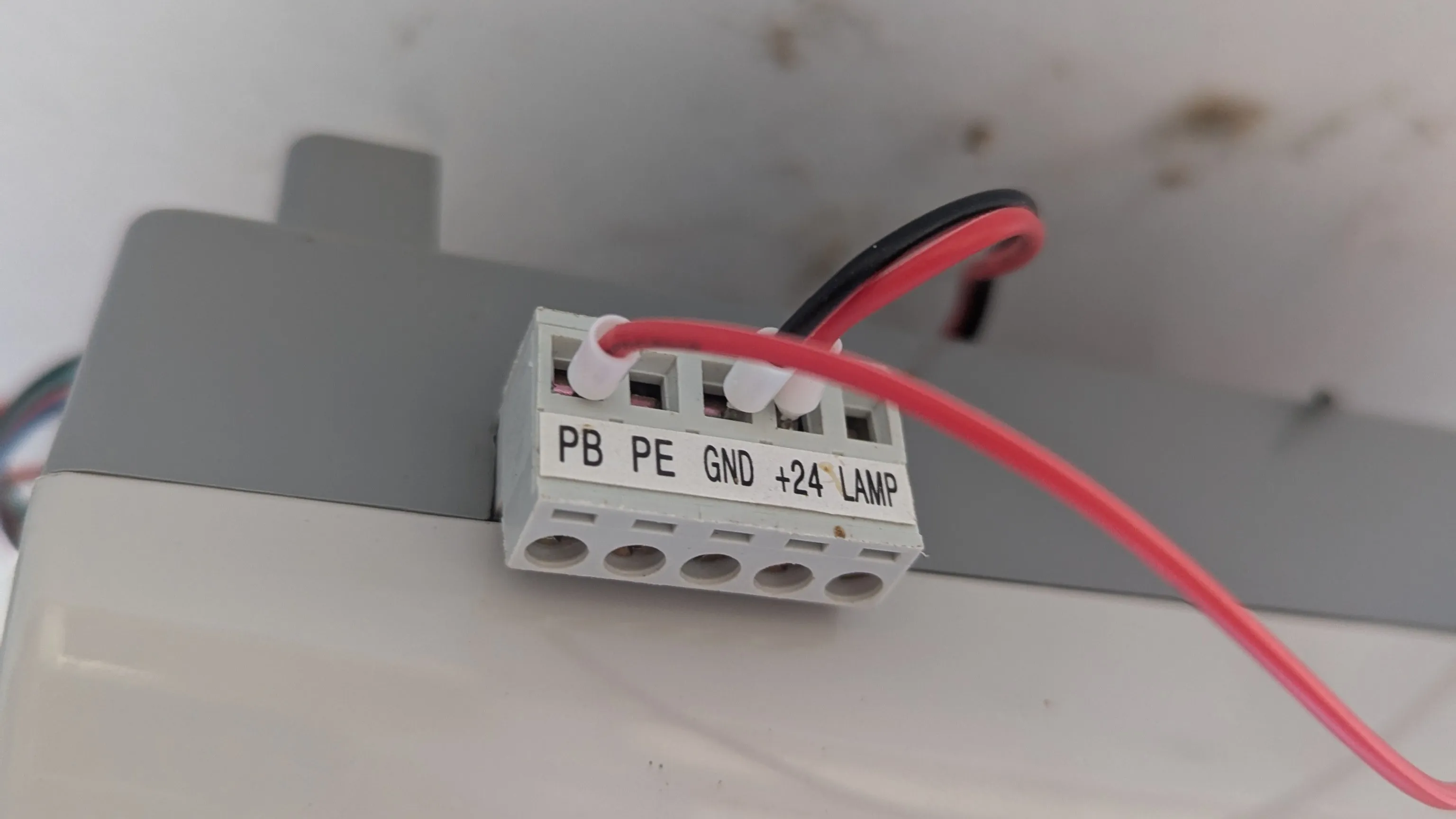
I had a spare ES32A08 relay/input board left over from a past modification to one of my laser cutters. Conveniently, I had a 24V model, and the JayTech controller exposes +24V DC power on the screw terminals. That seemed a little too good to be true…
Combined with some SN04-N inductive sensors (also left over from other CNC projects) which make up the limit switches, and also work on 24V, I had everything I need.
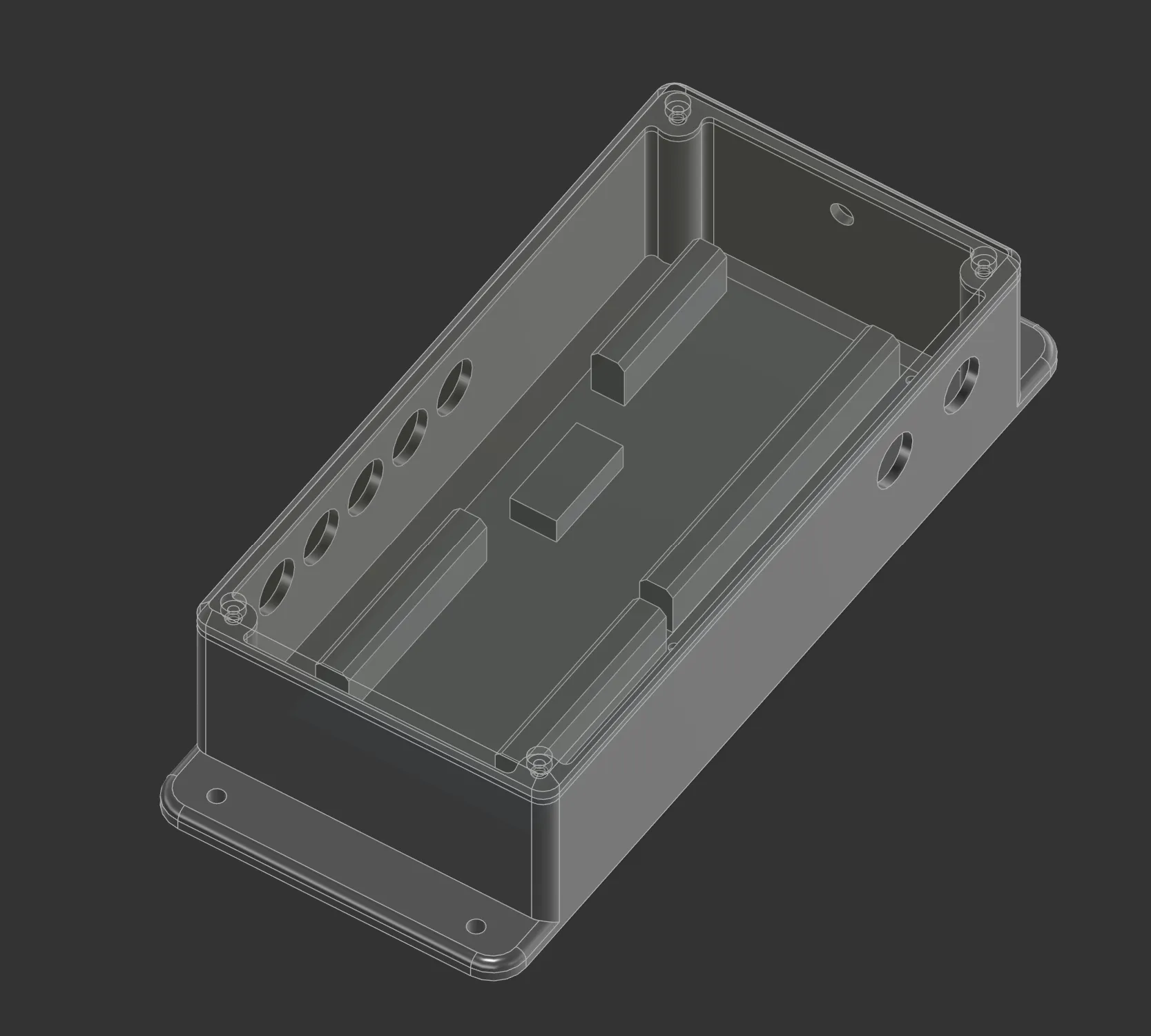
A simple 3D printed case to contain the board, and we’re set. The box was originally designed for the board to be used as a sprinkler controller, so it’s got extra holes, but given that the new application is indoors, I didn’t feel the need to reprint it just for this purpose. The design also includes a mock ES32A08 board used to align the holes. You can fetch the ES32A08 sprinkler box as STEP or ES32A08 sprinkler box as Fusion 360. The design is meant to have M3 heat set inserts and allows 4.5mm holes for this which fits the ones I happen to have.
I don’t have a photo of this one… as I wasn’t happy with the installation and how I routed the wires! But it’s safe and out of the way, I promise.
Software
I’m amazed by ESPHome as it already has kind of everything we need to get this to work. Technically it’s called a “cover” as far as Home Assistant is concerned, and it’s supported natively. There are a few variants of this in ESPHome, and after some experimentation, I found that the platform: feedback was the correct one for my use case, with the two limit switches on each end.
So let’s split this up into two parts. Firstly is the low level IO for the ES32A08 board. I stripped out everything other than what I was actually using - Output 1 for the push button, and input 3 and 4 for the “open” and “closed” position sensors.
For the “opener switch”, I used the on_turn_on to auto turn it off after 500ms. This simulates a “push” on the button. For the input sensors, I put a 50ms input filter to debounce the inputs.
# ES32A08 configuration
sn74hc595:
  - id: "sn74hc595_hub"
    data_pin: GPIO13
    clock_pin: GPIO27
    latch_pin: GPIO14
    oe_pin: GPIO4
    sr_count: 3

switch:
  - platform: gpio
    id: operate_door
    name: "Opener Switch"
    pin:
      sn74hc595: sn74hc595_hub
      number: 16
      inverted: false
    # Ensure it only turns on for 500ms then turns itself off
    on_turn_on:
      - delay: 500ms
      - switch.turn_off: operate_door

  - platform: gpio
    name: "status LED"
    pin: GPIO15
    inverted: True

sn74hc165:
  - id: sn74hc165_hub
    clock_pin: GPIO17
    data_pin: GPIO5
    load_pin: GPIO16
    sr_count: 1

binary_sensor:
  - platform: gpio
    id: open_sensor
    name: "Door Open Sensor"
    pin:
      sn74hc165: sn74hc165_hub
      number: 2
      inverted: true
    filters:
      - delayed_on: 50ms

  - platform: gpio
    id: closed_sensor
    name: "Door Closed Sensor"
    device_class: garage_door
    pin:
      sn74hc165: sn74hc165_hub
      number: 3
      inverted: true
    filters:
      - delayed_on: 50ms
And then comes the piece that connects it together: the cover. This took a few goes as you need to read the docs carefully about how it behaves - especially the has_built_in_endstop option!
cover:
  - platform: feedback
    name: "Garage Door"
    device_class: garage
    # Set to true so buttons don't disable if it "thinks" it's open/closed
    assumed_state: true

    # The door will stop itself, so don't trigger when it reaches the close position.
    # This defaulted to false - in which case, when the close stop triggers,
    # it runs "stop_action" and thus opens the door again! Setting this to true stopped this.
    has_built_in_endstop: true

    # Physical Endstops
    open_endstop: open_sensor
    close_endstop: closed_sensor

    # Timing (my door was slow...)
    open_duration: 40s
    close_duration: 40s
    max_duration: 60s # Safety cutoff for the timer

    # Actions (which all do the same thing).
    open_action:
      - switch.turn_on: operate_door
    close_action:
      - switch.turn_on: operate_door
    stop_action:
      - switch.turn_on: operate_door
Installation
So I delayed this project by a long time because I couldn’t decide where to put the endstop sensors where they were out of the way, and the wires wouldn’t interfere with the door itself, and it would reliably trigger.
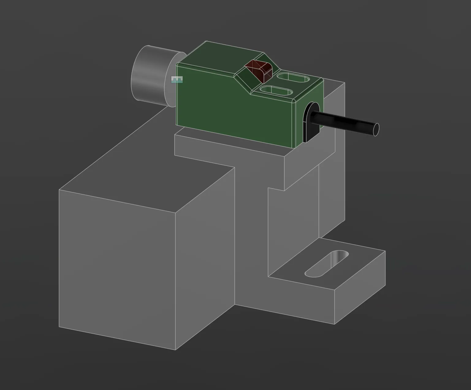
And then I saw the pin on the track pulling mechanism. A quick bit of modelling in Fusion 360 and a 3D print later (or in STEP), and I had a bracket to hold the sensor in exactly the right spot, but still allow some adjustment if needed. These are designed to have M3 heat set inserts installed in the top, to allow adjustment of the limit switch in place. These files work exactly on my rails, but will likely need adjustment for other rails.
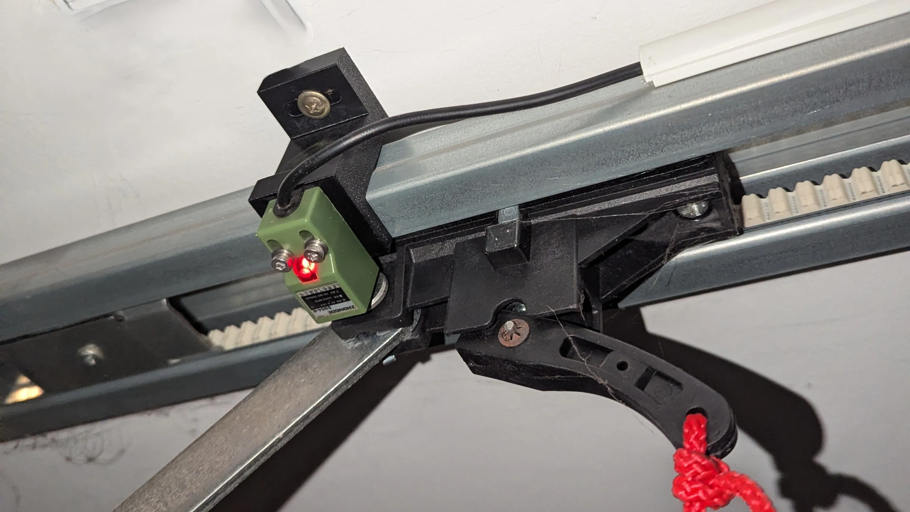
I naively thought that I could use the same bracket for both the open and closed position. But it turned out that the belt rail was offset from the ceiling on the front of the garage by 10mm - assumedly to get it to line up with the slightly out of square roof, concrete, and door. So the closed sensor was perfect, but the open sensor was too tall. In addition, there was a extra plastic tab on the belt puller bracket that caught the sensor…
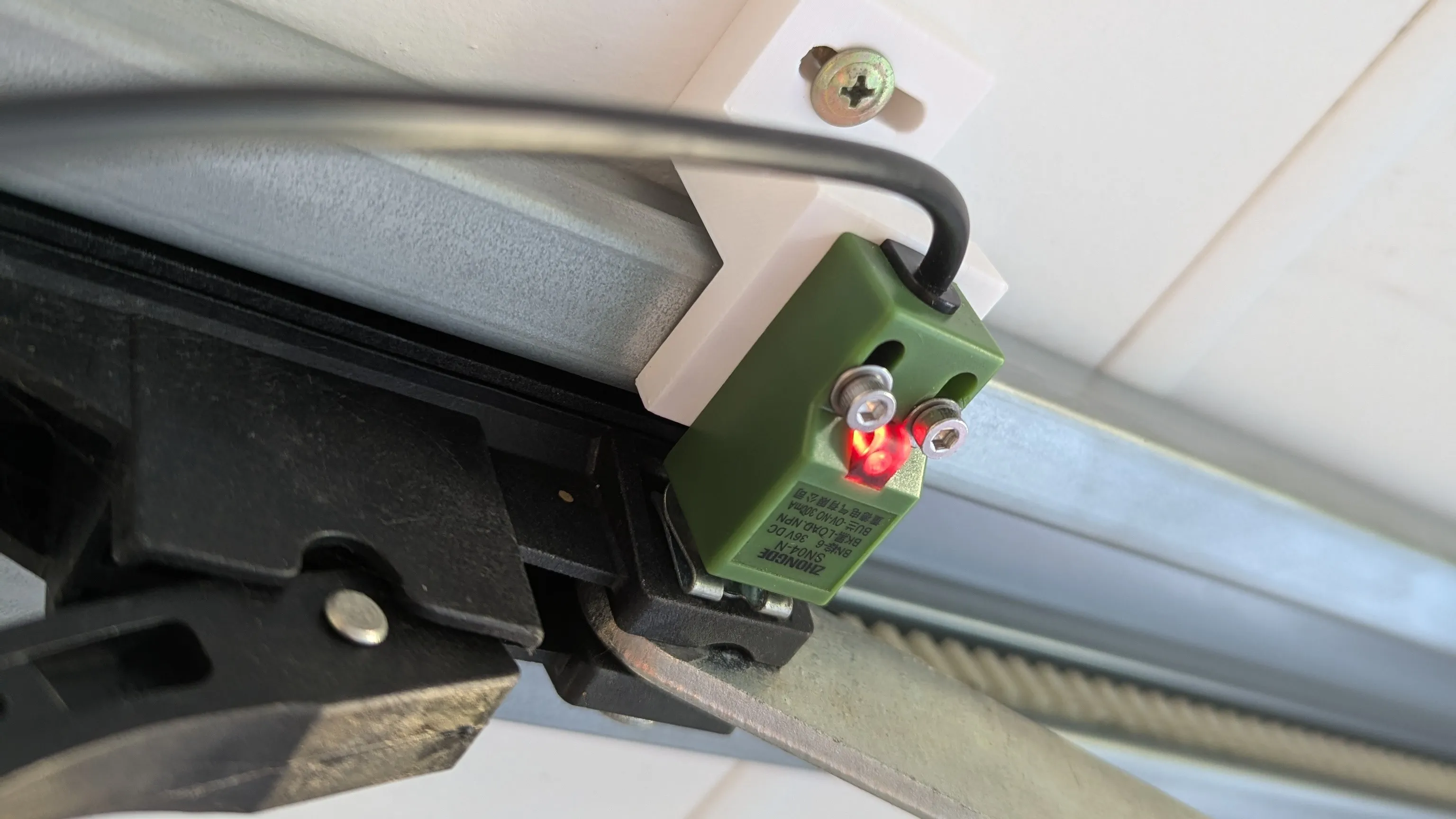
Turns out the back of the pin also contains metal, and without the extra plastic tab. So with a second 3D printed bracket, 10mm shorter, and placing the sensor on the opposite side, we had a working and reliably triggered open sensor.
Interference
The original garage remote controls work on 433MHz with a rolling code transmitter. Turns out that the 2.4GHz Wifi signal does interfere with it and significantly reduces the original remotes range!
I originally placed the ESP32 next to the garage door opener. Later on, I moved it further away (about 50cm back) and this significantly improved the original remote range. Something to keep in mind!
Result
There isn’t much else to say other than it works. My wife immediately asked me if I can automate it so when she gets close to home the door automatically opens. This should be possible as we’ve already got her phone hooked up to Home Assistant, but I’ll need to spend some time getting this reliably working. That’s the next step for another day!
Other than that - it does what it says on the tin!