The Long Clock
We have a home theatre room, and our two daughters (9 and 11) love nothing more than piling in for a movie or a few episodes of something together as a family. Which is lovely, right up until “just one more episode” turns into two hours and bedtime has quietly evaporated. Turns out we don’t actually have a clock in there at all which leads to the children losing track of time.
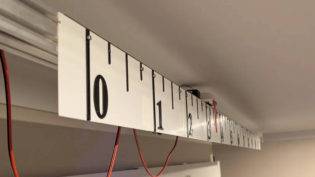
So I decided what was needed was a clock that was impossible to ignore. Not because it’s loud, or has an alarm, but because it’s enormous, mechanical, and slightly unsettling to watch - a carriage silently and visibly crawling across a 2.3 metre track, one tick at a time, so that even two kids glued to the TV can tell roughly how much of the hour has gone without anyone having to say a word.
Enter the Long Clock: a single-axis CNC machine, repurposed to do nothing but tell the time, badly disguised as a piece of industrial equipment mounted overhead on the ceiling.
Hardware
The whole point of this project was to use what I already had lying around rather than buy anything new, so the bill of materials reads a bit like an inventory of my spare parts bin:
- A 3000mm length of 40x40 V-slot aluminium extrusion, salvaged from a much bigger CNC machine that had been decommissioned and was no longer needed.
- Three 800mm sections of MGN9 linear rail, because that’s what I had on hand rather than one continuous 2.4m rail.
- An MKS-DLC32 controller board, which is a cheap ESP32-based board originally intended for small CNC routers and laser cutters, running a modified fork of FluidNC called FluidNC-as-long-clock.
- A custom rack and pinion drive that I’ve been fiddling with and refining for years, more on that below.
- A NEMA23 stepper, an optical endstop, cable clips, and various M5/M3 hardware, all salvaged from previous builds.
I have absolutely no idea how it happened, but I’ve somehow accumulated several spare MKS-DLC32 boards over the years, along with a few of the larger MKS TinyBee boards, none of which currently have a home in any other project. This build finally gave one of the DLC32s a job to do. The TinyBees remain unemployed, patiently waiting for me to think of something suitably ridiculous for them too.
Since it only needs to move in a straight line, this is about as simple as a CNC design gets - just the one axis, no gantry, no tool head, nothing to calibrate other than steps-per-mm.
Designing it in Fusion 360
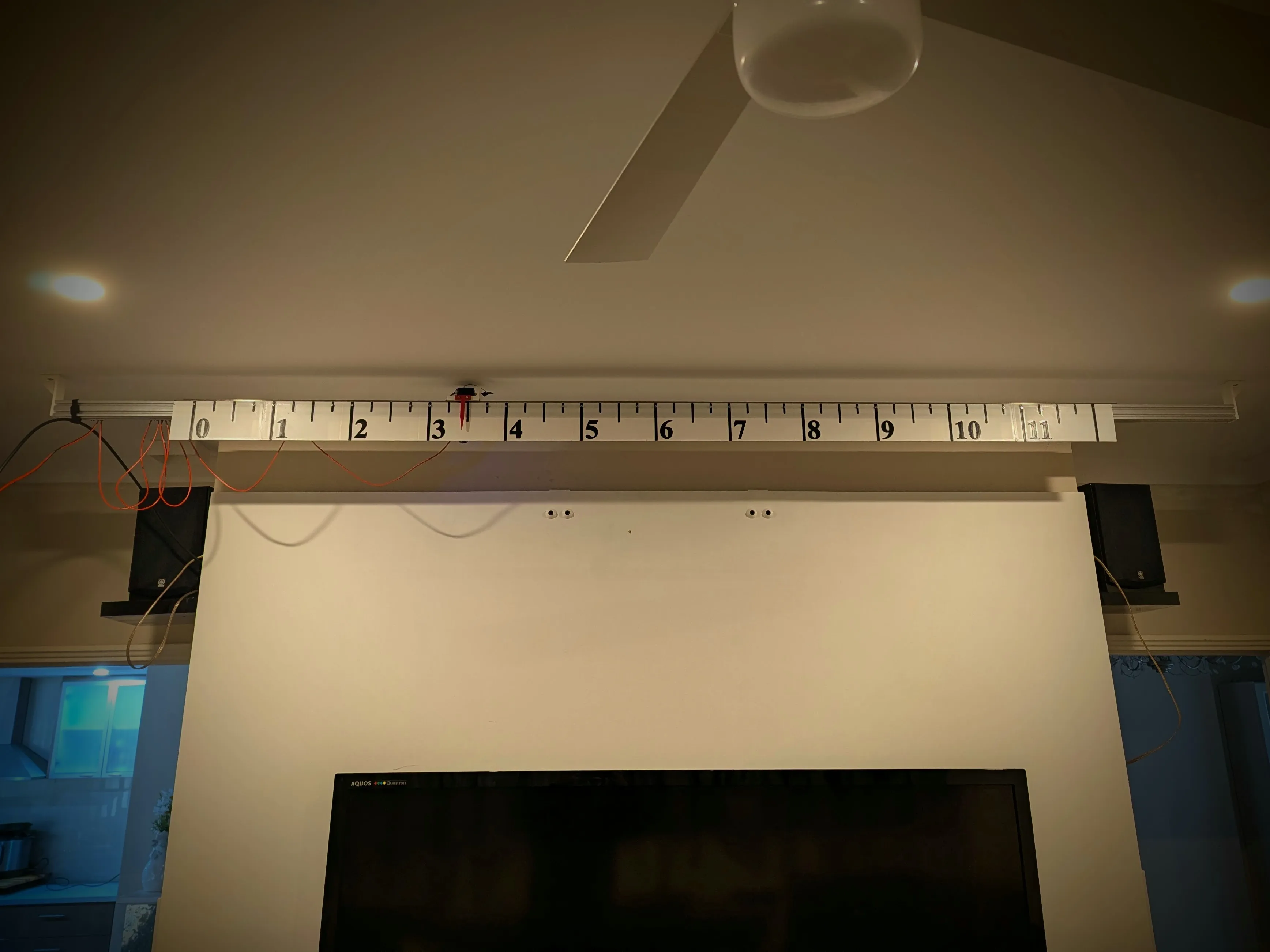
The whole mechanical assembly - carriage, hand mount, endstop bracket, rack segments, the lot - was modelled up in Fusion 360 before anything got printed. It’s not the most polished parametric model I’ve ever built, but it does exactly what I actually needed it to do: accurately capture where every part sits relative to the extrusion and each other, and how they all line up, so I could confidently print things and have them actually fit together on the first go rather than discovering a clash after the fact.
That was the whole point of doing it in CAD in the first place - with almost 3 metres of travel and sixteen individually printed rack segments all needing to land in exactly the right spot relative to the carriage and endstop, getting the alignment right in the model meant getting it right in real life too.
For anyone curious enough to poke through it, I’ve included both the STEP file and the native Fusion 360 archive in the post files.
The rack and pinion
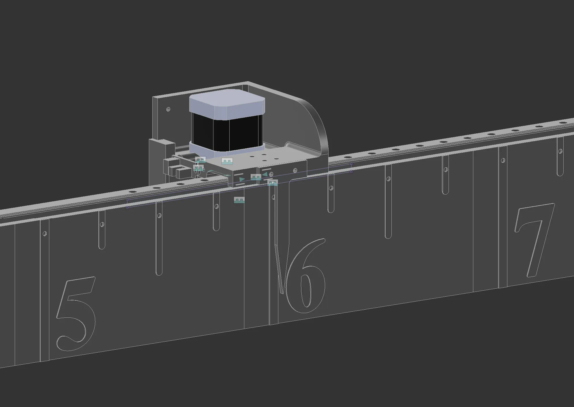
The drive mechanism is the one part of this build that isn’t “off the shelf” in any sense. I’ve had a rack-and-pinion design kicking around in Fusion 360 for a long time now, one of those side projects I keep coming back to and refining a little more each time. It’s designed to slide directly into the V-slot groove of the extrusion, meaning the extrusion itself acts as both the structural rail and the rack housing - no separate rack profile to source or mount.
Each printed section is about 180mm long, and they simply butt up end to end to form a continuous rack for as long as the extrusion runs. For this build that meant right around sixteen segments printed and clicked into the groove, one after another, to cover the full 3 metres.

The three MGN9 rail sections actually butted together very accurately - I was pleasantly surprised there was no detectable step or misalignment at the joins after 2.4m of travel. The pinion being a 3D printed part rather than a machined one is a different story though, and that’s where the real hardware quirk I had to design around in software comes from - more on that shortly.
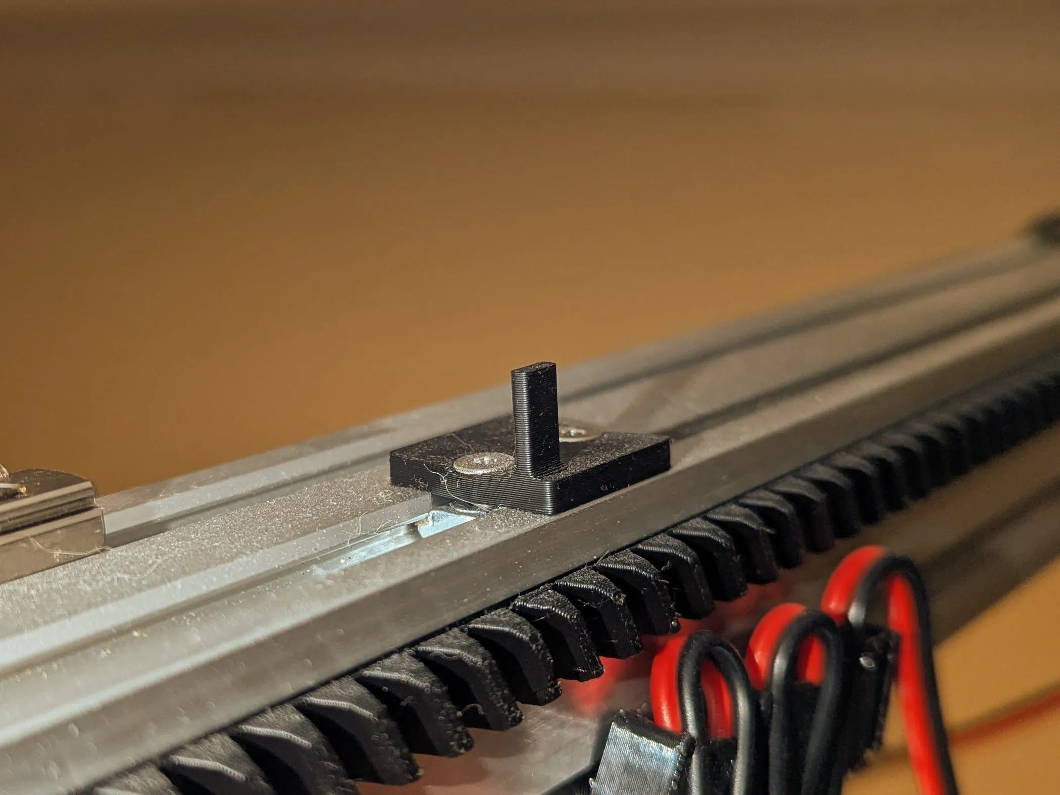
Cable management and the end stop
With almost 3 metres of travel, I really should have designed and printed a proper drag chain to carry power and signal to the carriage. But if I’m honest, I couldn’t be bothered. Instead I went with the lazy version: a run of plastic clips pushed straight into the V-slot groove alongside the rack, with the cable simply looped and gathered up as the carriage travels back and forth - loosely inspired by the way giant overhead gantry cranes in warehouses let their cables spool and unspool in big loose loops rather than running through a proper chain. It’s not elegant engineering, but it works, and it took about ten minutes instead of an afternoon of drag chain design.
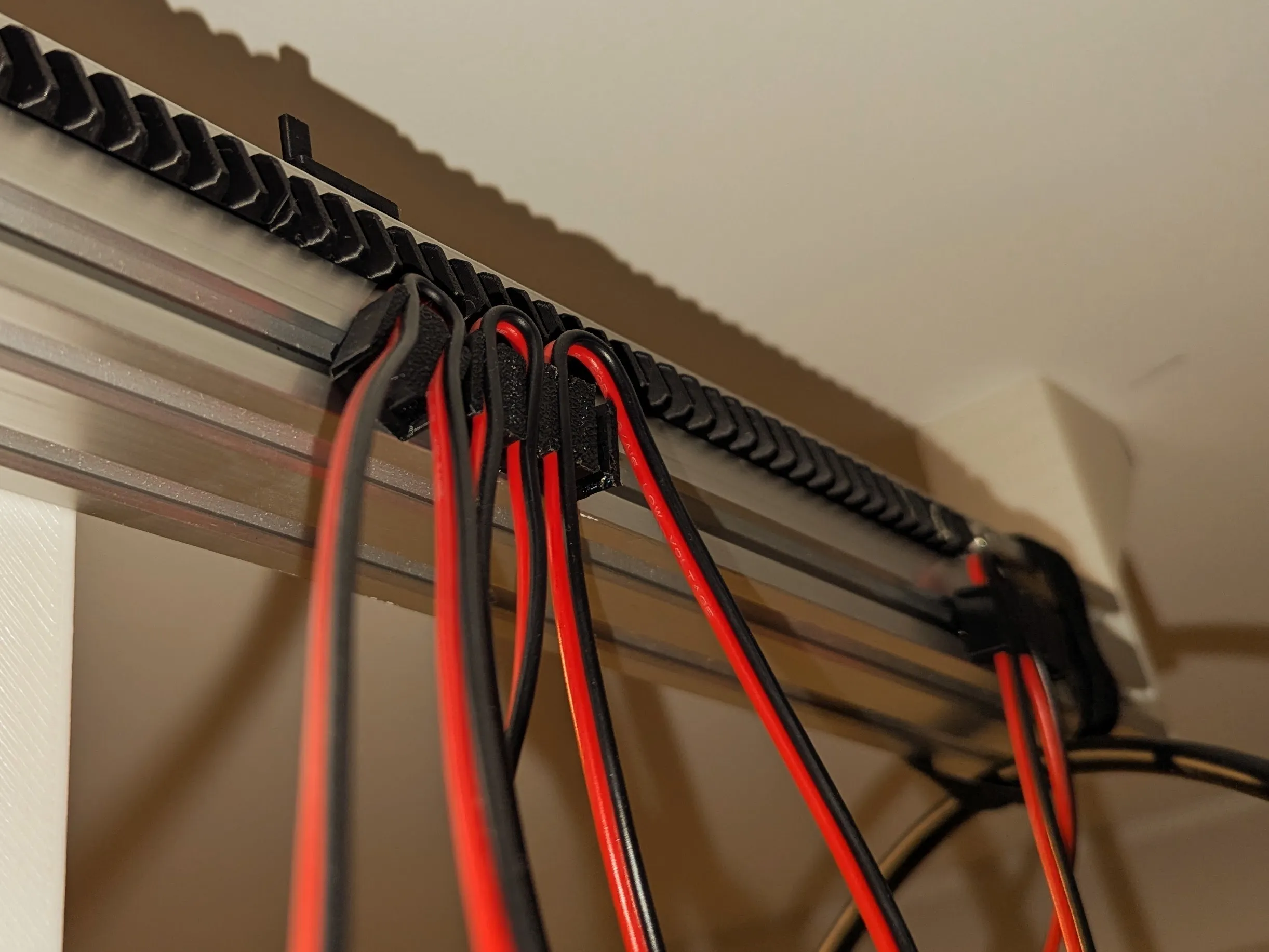
Homing is handled by a single optical endstop at one end of the travel, wired into the DLC32’s inputs the same way you’d home any FluidNC axis. I went with optical over a mechanical microswitch mostly because I had one spare from a previous build, but it’s also nice not to have anything physically flexing and wearing out after tens of thousands of homing cycles.
The face
The “clock face” itself is just a long printed strip mounted along the extrusion, with the carriage carrying a hand/pointer that runs along in front of it.
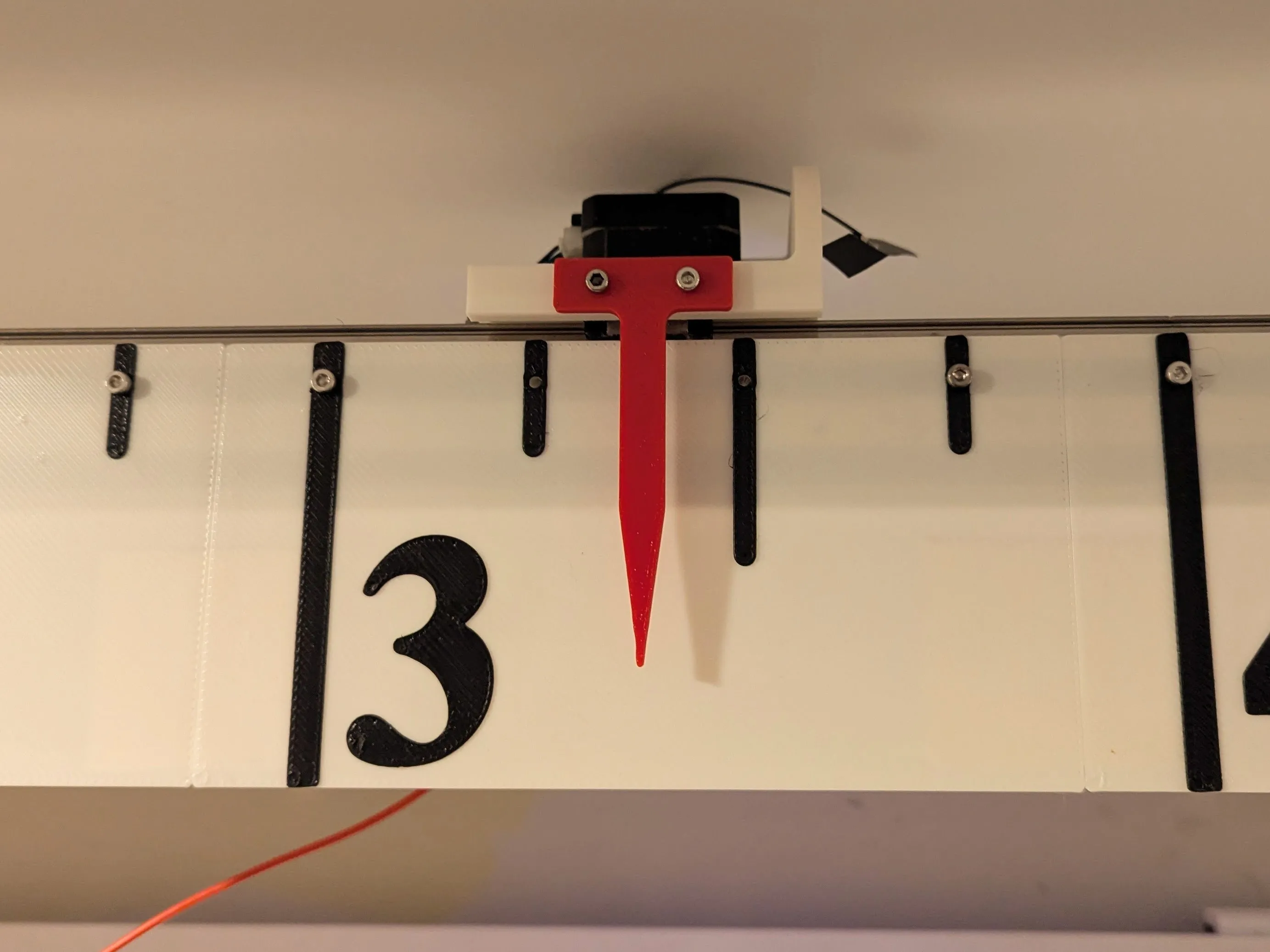
I designed the front panel graphics in Adobe Illustrator rather than modelling hour markings and numbers directly in Fusion 360 - Illustrator is simply much better at typography and precise text layout than any CAD package I’ve used. Went with an olde-worlde Times New Roman for the numerals, because if you’re building an absurdly oversized mechanical clock, it may as well look faintly Victorian about it. Once the artwork was done, I imported the vector geometry back into Fusion 360, extruded it into an actual 3D object, and printed it with a 0.8mm nozzle for speed. It’s not going to win any design awards up close, and the print lines are visible if you go looking for them, but from across a room it reads perfectly well as a clock face, and that’s really all it needed to do.
Software
My first instinct was that I’d need some separate always-on computer (a Raspberry Pi, or similar) to keep proper time and push position updates over serial or network to the DLC32, since FluidNC itself has no concept of “what time is it” - it just runs G-code. But before going down that path, I had a poke around inside FluidNC’s source to see how hard it would be to just teach the controller to know the time itself.
Turns out it’s not hard at all. FluidNC already has a clean extension point for exactly this kind of thing (ConfigurableModule, see FluidNC/src/Module.h) that lets you register new modules which get configured straight from config.yaml and polled on the same loop as everything else in the firmware. So rather than bolt on an external device, I forked FluidNC and added two small modules directly into it - LongClockSNTP and LongClock - and now the whole thing keeps its own time and drives itself, with nothing else needed on the network except a WiFi access point. You can find the full source for the fork at freefoote/FluidNC-as-long-clock on GitHub.
LongClockSNTP is the simple half - it wraps the ESP32’s built-in SNTP client, syncs against an NTP server on a configurable interval, and exposes a heuristic isSynced() (basically: “is the system year greater than 2020?”) since there’s no proper sync callback readily available.
LongClock does the actual work. Once a minute ticks over, and assuming the machine is Idle (i.e. not running a job or being jogged), it computes a target position from the current time and issues a G-code move to get there:
// Simplified from LongClock.cpp - map the current time onto the travel range
float LongClock::timeToPosition(int hour, int minute, int second) {
    // 12-hour mode wraps at 12:00/00:00, 24-hour mode covers the full day
    float cycle_seconds = twelve_hour_mode ? (12 * 3600) : (24 * 3600);
    float elapsed = (hour % (twelve_hour_mode ? 12 : 24)) * 3600 + minute * 60 + second;
    float fraction = elapsed / cycle_seconds;
    return pos_start_mm + fraction * (pos_end_mm - pos_start_mm);
}
The actual machine config for this build lives in mks-dlc32-long-clock.yaml, and the relevant section looks like this:
long_clock:
  enabled: true
  twelve_hour_mode: true
  pos_start_mm: 3
  pos_end_mm: 2235.0
  use_rapid_moves: false
  feed_mm_per_min: 3000
I deliberately used a fed move (G90G1F3000) rather than a rapid move. A rapid move would just snap the carriage instantly to the new position each minute, which looks abrupt and honestly a bit alarming to walk past. A fed move means it visibly “ticks” across the face over a second or two, which reads much more like an actual clock mechanism doing its job, and much less like something malfunctioning.
Getting out of sync (and fixing it)
Here’s where those printed rack segments come back to bite me. Stepper positioning on this axis isn’t perfectly reliable - over enough cycles, small amounts of step loss (almost certainly from the pinion occasionally skipping a tooth at a segment join in the 3D printed rack) would accumulate, and the clock would drift further and further from the actual time. Annoying on a clock whose entire purpose is to be glanced at and trusted at a glance.
My first version only homed once, on boot, and then just trusted the stepper positioning from there on out. It didn’t hold up - the drift accumulated visibly over the following days, and by the end of a week it was a good 20 minutes off.
So the fix I landed on is blunt but effective: every time the cycle wraps back around to its start (00:00, or 00:00/12:00 in 12-hour mode), instead of moving to pos_start_mm like any other minute, the machine re-homes the X axis entirely. Homing re-establishes a true zero against the optical endstop, which corrects for whatever drift crept in since the last homing before it has a chance to compound further.
As a bonus, this also gives me automatic recovery from Alarm states - if the
machine ever trips a limit or loses its mind mid-cycle, LongClock will
notice it’s in Alarm on the next poll and attempt to re-home to clear it and
get back to tracking time unattended, without me needing to walk over and
intervene.
It’s not an elegant fix for the underlying mechanical drift, but it bounds the problem neatly: worst case, the displayed time is only ever off by however much it can drift in a single 12-hour cycle, and then it snaps back to dead accurate. Given the audience is two kids glancing up at the ceiling between episodes, “dead accurate at least once every 12 hours, gradually drifting in between” is more than good enough.
I’ve now had this running for several months, and it’s working well - homing at the end of every complete cycle means that, in the 12-hour mode it’s currently running in, it corrects itself twice a day. That’s frequent enough that the accumulated drift never gets the chance to become obviously visible before it’s wiped out again.
Building and flashing
If you want to build the firmware yourself, it’s the usual PlatformIO dance:
# On the dev machine, from the FluidNC fork
desktop$ source .venv/bin/activate
desktop$ uv run pio run
That spits out firmware.bin under .pio/build/wifi/, which gets flashed to the MKS-DLC32 exactly as you would for a stock FluidNC install. Then it’s a matter of uploading mks-dlc32-long-clock.yaml as the active config.yaml (via the FluidNC web UI works fine), connecting it to WiFi, and letting it home and start ticking on its own.
Electronics (or lack of a proper enclosure)
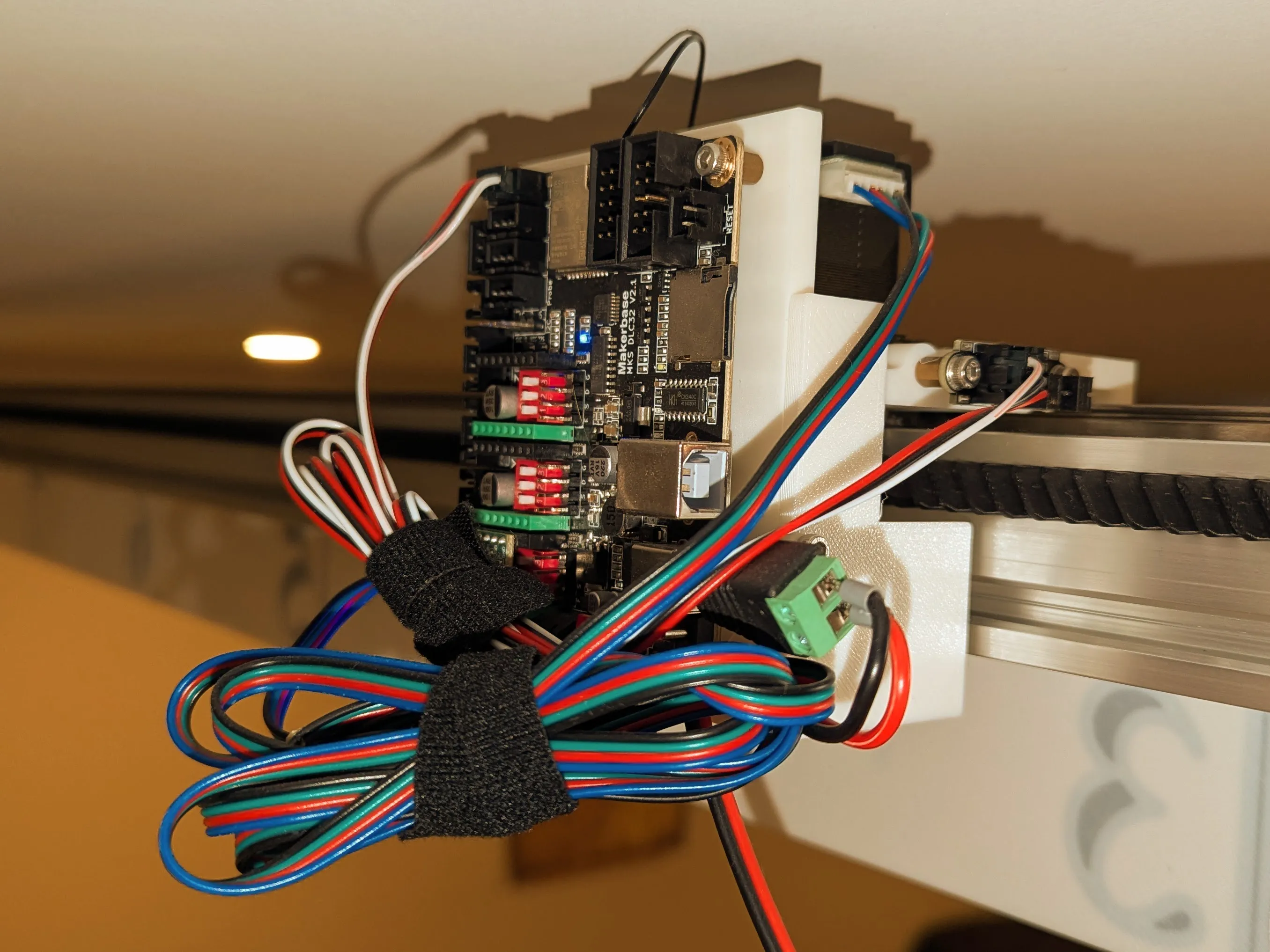
Because this thing lives on the ceiling and is meant to be left completely alone, I didn’t bother with any extra buttons or displays beyond what FluidNC already gives you over its web interface - the DLC32 sits on WiFi and I can check on it, or manually home it if I’ve been fiddling with the rack, from my phone.
I also, if I’m honest, didn’t bother with a proper enclosure for the electronics either. The DLC32 board is just screwed straight onto the back of the extrusion mount, bare, out in the open. All the excess wiring is very roughly tidied up with a handful of Velcro cable straps rather than routed through anything resembling a tidy loom. It’s not pretty, and I definitely wouldn’t want small fingers poking at it, but being up on the ceiling keeps it well out of reach anyway, and “good enough” won out over “properly finished” once again.
Result
It’s mounted on the home theatre ceiling now, ticking along one tick per minute, homing itself twice a day whether anyone’s watching or not. Nobody can ignore nearly 3 metres of aluminium extrusion with a carriage crawling along overhead - which was rather the point.
Things I’d improve if I did it again:
- A proper machined or moulded pinion (and rack) rather than 3D printed ones, for a bit more long-term reliability between homing cycles - this is almost certainly the actual source of the drift that made the re-homing fix necessary in the first place.
- A slightly nicer face panel - the 0.8mm nozzle print is functional, not pretty, and it shows if you get close enough.
But for now, mounted overhead, doing exactly one job and doing it reliably twice-daily-corrected: it does what it says on the tin. The kids’ reaction was a lot more understated than I expected - no grand pronouncements, they just quietly started glancing up at it and using it, easily and correctly, to tell how much time had passed during a movie or a binge session. Which, thinking about it, is exactly the reaction I actually wanted; a clock that just works and gets used without anyone having to think about it is a better result than one that gets a round of applause and then gets ignored.
I was honestly a little nervous about what my wife would make of a giant CNC contraption bolted to our home theatre ceiling. Surprisingly, she was completely fine with it - more than fine, actually happy with the result - which I wasn’t expecting at all going into this one.