
TV Backlight - 2025 Version
All the way back in 2013, I hacked together a system to provide an Ambilight style system for my new home’s TV, based on capturing the screen of the computer driving it and writing it out to WS2812B LEDs.
About two years later, for a variety of reasons, we moved away from using a PC for this and switched to various media appliances, specifically the Google Chromecast, and then onto Google TV. They “just work” in this modern copy protected and subscription based landscape. But the little quirk that prevented a new system from working was HDCP - we couldn’t easily capture the image on screen to format for the backlight LEDs. I’d call it fair use, but obviously this can be abused in other ways, and as such is not permitted.
So the system lay dormant and gathering dust for quite some time, and due to standard adult life constraints like working and children, it didn’t go anywhere. Every 12 months or so I’d think about it again, do some quick searches to see what was possible, decide it wasn’t feasible, and then leave it again.
2025
So what has changed now? A few month ago my wife asked about it again, and due to some other changes in life circumstances giving me a little more free time recently, I did a deeper research than I normally would on this matter.
And this turned up HyperHDR. Which I immediately identified as a well written, very advanced, and very workable solution to this. And it’s open source to boot - an amazing contribution to the general community! But I had to pony up a little bit of cash for some parts to make it work - but I felt it was worth the risk to try it out again.
TL;DR: The result
Components
Following their really well written Ultimate guide on building an LED system, I went with the following components:
- Raspberry Pi 4 (which I already had left over from another scrapped project)
- A MS2130 USB3 HDMI Capture Dongle (via Aliexpress)
- A FeinTech VSP01201 HDMI splitter (via Amazon)
- An WT32-ETH01 board - ESP32 with ethernet board (via AliExpress)
- A 10A/5V power supply (which was spare from another project)
- WS2812 x 5m LED strip, 30 LEDs/meter (reused from the original TV backlight from 2013; it was still stuck to the TV in the right locations and I felt no need to replace it!)
And the hardware it works with:
- A 2012 model Sharp 70” Dumb TV - 1920x1080 - still going strong with extensive daily use and I currently feel no need to replace it! (Why don’t they make Dumb TVs anymore? That’s a gripe for another day.)
- A 2012 model Yamaha RX-V473 receiver for audio - also still going strong and I also feel no need to replace it at this time!
- A 2023 model Google TV dongle.
Connections
So the connections go like this:
- Google TV -> Yamaha Receiver
- Yamaha Receiver -> HDMI splitter
- HDMI Splitter to TV and also to USB capture device
- USB Capture device to Raspberry Pi
- Raspberry Pi to WLED on Ethernet WT32-ETH01 board
---
config:
  theme: 'dark'
---
flowchart TB
    A[Google TV] e1@==> B[Yamaha Receiver]
    B e2@==> C[HDMI Splitter]
    C e3@==> D[USB Capture Device]
    C e4@==> E[TV]
    D e5@==> F[Raspberry Pi 4]
    F e6@==> G[WLED on WT32-ETH01]

    e1@{ animate: true }
    e2@{ animate: true }
    e3@{ animate: true }
    e4@{ animate: true }
    e5@{ animate: true }
    e6@{ animate: true }
LED Setup
My original setup used an Arduino Uno with an ethernet shield, and surprisingly, this worked fantastically for the number of LEDs on the screen that I have (144) and handled 30fps without issues. It also helped that 144 LEDs x 3 bytes per pixel = 432 bytes, well within the UDP packet size limits, and also comfortably in the Arduino Uno’s RAM (1536 bytes).
With HyperHDR, they recommend an ESP32 connected to the Raspberry Pi with SPI for best transfer rates. I like the concept, but I’m lazy and didn’t want to handle the custom flashing required - I’m too used to WLED and being able to connect it via a web browser and flash it… and HyperHDR does support writing to WLED for the hardware, along with their very extensive output list.
So I opted to purchase a WT32-ETH01 board instead, intending to get the pixel data to the ESP32 running WLED via ethernet, to remove any Wireless oddness. I forgot that this board didn’t have on board USB, but a USB to serial adapter made short work of the programming. Once flashed, you do need to connect it to WiFi first, and then configure the board in WLED to enable Ethernet, and also choose a different GPIO pin for the WS2812 LEDs like I had to, as the default pin 16 was used by the ethernet hardware. But it was worth the effort.
I chose not to use a level shifter although technically I should have of as the ESP32 uses a 3.3V output signal and the LEDs expect 5V, but I kept the wires between the ESP32 and the LED strip short, and the WS2812 does have a signal regenerator in each chip, so as long as it gets to the first chip, we should be good. Basically the “hope for the best” approach.
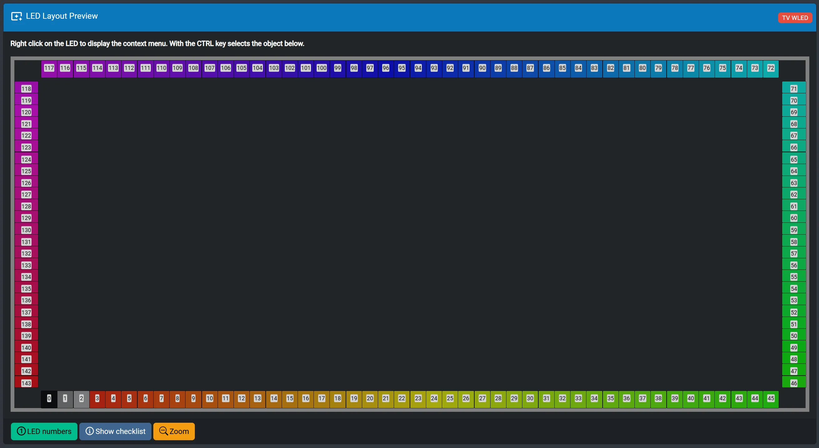
The LEDs on the TV were arranged how they were originally; starting in the bottom left (looking at the front of the TV), going up 26 LEDs, across 46, down 26, and across 46 to complete the loop. A beefy 10A/5V power supply gives just enough power for this strip of LEDs at full tilt, although they wouldn’t normally use that much power. (144 LEDs x 60mA each = 8,640 mA if they’re all white at the same time).
I ended up adding gaps to the corners to better represent where they were on the TV (the “Edge Gap” setting, set to 12% did the trick) ad reversing the LED direction to get them to render correctly.
Weird captured colours
HyperHDR very conveniently supplies a “Live Preview” through the web console, which is fantastic for debugging. The first issue I noticed was the the captured image had a very pink tinge. After a bit of Googling, it was suggested that this was something to do with the capture colour mode. After trying a bunch of capture settings in HyperHDR, I wasn’t able to eliminate it. This was only from the Google TV, although I hadn’t tried any other video sources as this was the only video source I intended to use.
So I thought in a different direction. I went through through the Google TV settings, and it has a HDMI colour output format. The default is “YCbCr 4:4:4 8-bit”. But underneath that is “RGB 8-bit”. Surely it can’t be that simple? Yes - it was - set it to “RGB 8-bit” and the capture instantly had the correct colours. I’m not full bottle on video colour formats, so I’m sure some more knowledgeable person is shaking their fists at me for destroying the colour gamut. But given the old equipment I’m not using HDR or any of those newer fancy innovations, combined with my lack of perfect vision, means that it still looks good to me.
Later on, I connected a Nintendo Switch to the system, but this worked perfectly immediately and with the correct colours. So it must be a Google TV quirk.
Wall mount
We already had the TV wall mounted from when it was first installed. Our theatre has a bit of a recess for the TV to sit in, which with the original one, lit up quite well. But it did constrain the effect to that recess.
So for this round, I made the TV come out as far as it could from the wall. And then experimented with a white roller blind behind it to capture and spread the light instead of having it disappear inside the well. With mixed results!
After several iterations of shelves over the years for the Hifi gear and having large speakers next to the TV, blocking my glorious backlight, we simplified. All the Hifi gear went onto a wall mounted shelf behind the TV so it wasn’t visible. The giant speakers were moved to the back of the room, and the smaller back speakers were then wall mounted high up near the doors. The center speaker was left behind the TV, and we removed the subwoofer entirely. I can see some audiophiles shaking their heads (including a close friend who looked quite shocked when I told them), but we’re not audiophiles and are happy to live with something not perfect, but still sounds great to us.
One little quirk of putting everything behind the TV was that there was no infrared line of sight to the receiver to change the volume. We had been using the Google TV’s programmable remote for this, as it has a built in IR transmitter and you can configure it for your equipment. But it turns out that wasn’t much of an issue to fix; switch the Google TV into HDMI CEC mode for volume control. But then it still didn’t work… the Yamaha receiver also needed a setting to enable “HDMI control” - and then it worked perfectly. Problem solved!
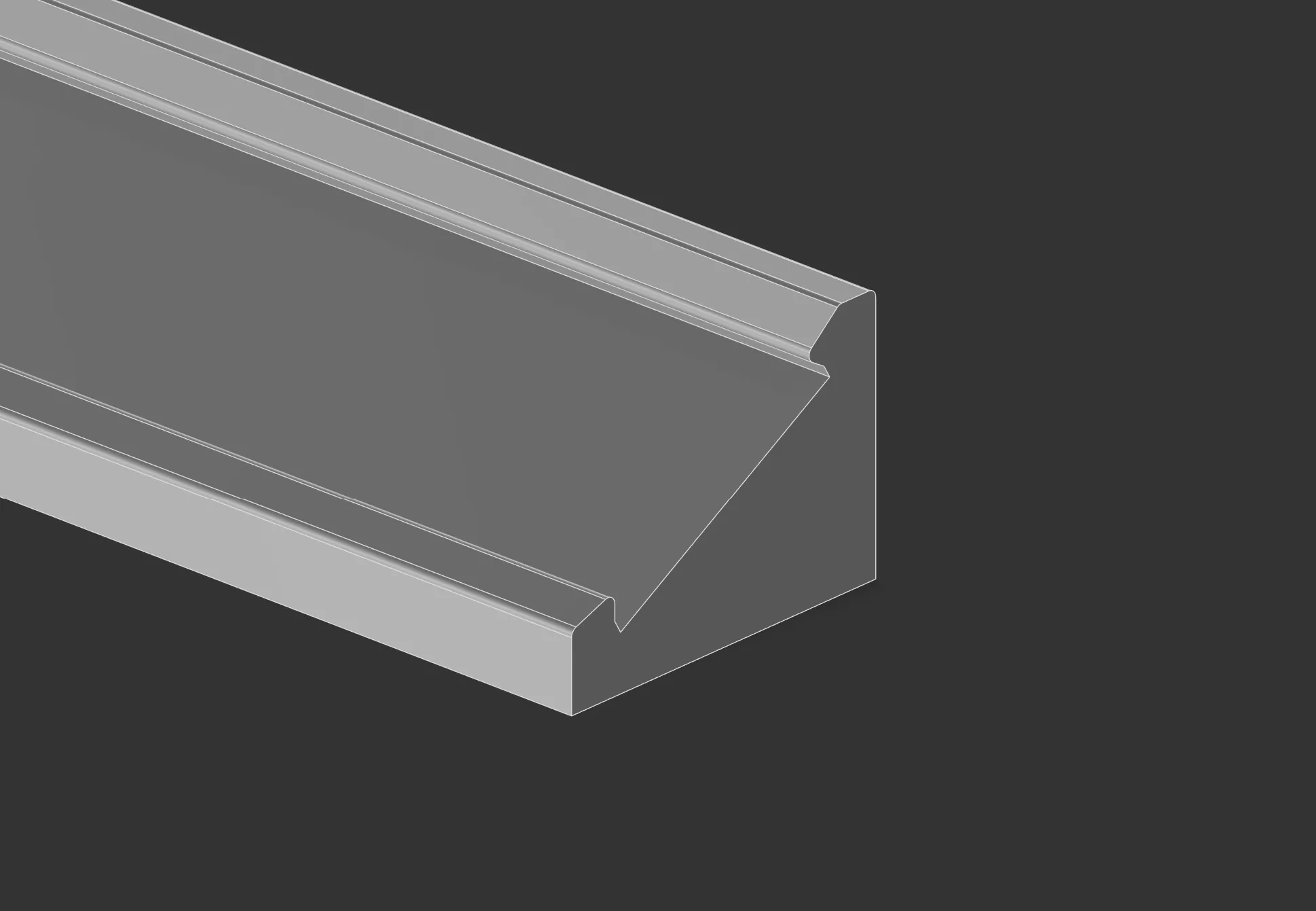
The final part of the solution was to 3D print some angle slots to direct the LED light away from the TV somewhat to better work with the blind. These are designed to have an exactly 10mm wide slot and a slight lip to catch the LED string. To mount them, I used blu-tac which worked great on the TV. The angles of the strip clips were designed such that it didn’t need any supports when printed with the largest flat surface on the print bed. They were designed them at 30 degrees which seemed to work well. I’ve got the Fusion 360 design for these here if you want to adjust it, or a static STEP version if you just want to print it as-is.
The roller blind
So to cover up the recess, and hide all the uglyness, and to provide a flat nice surface to project the LEDs onto, we installed a roller blind onto the wall. We ended up purchasing one that was 2400mm wide (giving about 50mm left on each side on the wall) and that had a 2400mm drop. Our high ceilings in the theatre were taller than this, so I ended up mounting it 2300mm above floor height, to allow it to comfortably sit on the floor.
To get it to be behind the TV, we had to cut it. The aluminium bar on the bottom was able to slide off, so that was easy to cut with a hack saw. Then, the blind itself was laid over the front of the TV temporarily, and marked up for cutting. Some nice fabric scissors made for a nice straight single cut in the middle underneath, and then we cut a circular section behind the middle of the TV to go around the wall mount bracket. After some minor adjustments to the size of the hole behind the TV, it was in place…
The slit in the blind at the bottom was resolved with some 3D printing magic and some magnets to keep it together.
After I showed a close friend the setup, they pointed out I could have actually taken the TV off it’s mount, cut a single hole in the blind to get it over the TV mount, and then put the TV back on. Thus meaning I didn’t need to cut a slit in the blind. Oh well… it’s done now, and it doesn’t look terrible.
Future
Well, ths blog post got a bit delayed. We’ve now been using it for 2 months. It’s become a part of the TV. We’re pretty happy with it.
The last thing I need to fix is to get the blind edges to bond to the wall a bit better, in a way that can be removed for maintenance. The cats like going back there (sigh) so it would be nice to close that off. I’m working on it.
Otherwise - we’re enjoying it!